Multifunctional transformer used for traction transmission system

A traction drive, traction inverter technology, applied in control systems, electrical energy storage systems, control/regulation systems, etc., can solve problems such as train speed loss, equipment damage, and increase in traction network voltage, to reduce volume and The effect of weight, improving energy utilization, reducing speed loss

Active Publication Date: 2015-09-23
CSR ZHUZHOU ELECTRIC LOCOMOTIVE RES INST
View PDF5 Cites 3 Cited by
  • Summary
  • Abstract
  • Description
  • Claims
  • Application Information

AI Technical Summary

Problems solved by technology

[0006] (1) The volume and weight are large, which affects the passenger capacity and high-speed performance of the train, especially on EMUs with dispersed power. The limitation of installation space makes the impact of transformer volume and weight particularly prominent;
[0007] (2) The output voltage of the power frequency transformer will change with the change of the load, and the drop of the output voltage will bring difficulty to the transmission control;
In this way, the train will have a speed loss;
[0009] (4) Power frequency transformers need to use cooling oil, which is easy to cause pollution to the environment
[0010] (5) When the train is braking, it will generate a lot of feedback energy. If the braking energy is not effectively used, not only will the energy utilization rate of the traction network be low, but the braking energy will also increase the voltage of the traction network abnormally. , resulting in equipment damage

Method used


Image

  • Multifunctional transformer used for traction transmission system
  • Multifunctional transformer used for traction transmission system
  • Multifunctional transformer used for traction transmission system

Examples


Embodiment Construction

[0031] The present invention will be further described in detail below in conjunction with the accompanying drawings and specific embodiments.

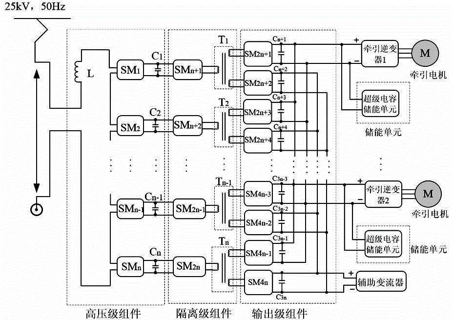
[0032] The multifunctional transformer used for the traction drive system of the present invention is based on the electronic power transformer technology; as figure 2 As shown, taking the specific application of a transformer with two traction motors as an example, the transformer includes:

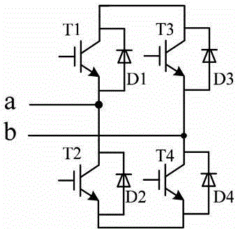
[0033] The high-voltage level components are connected to the railway traction network with an AC voltage of 25kV by connecting the reactance L, and are cascaded by cascading n-level bridge-type power sub-modules (SM1-SMn, Submodule). The circuit diagram of the power sub-module SM is as follows image 3 As shown; each H-bridge is connected in parallel with a capacitor (C1-Cm) of the same capacity, and the capacitor has the function of energy storage and filtering. The H-bridge module converts the AC voltage it bears into a DC voltage across th...


PUM


Abstract

The invention discloses a multifunctional transformer used for a traction transmission system. The multifunctional transformer comprises a high-voltage stage assembly connected into a traction network, wherein n stages of identical bridge-type power sub-modules are cascaded to form the high-voltage stage assembly; an isolation stage assembly, wherein the isolation stage assembly comprises more than one high-frequency modulation circuit and more than one high-frequency transformer, the high-frequency modulation circuits modulate a direct voltage converted by the high-voltage stage assembly into a high-frequency square-wave voltage, and the high-frequency square-wave voltage is coupled to two windings on a secondary side through the high-frequency transformers and is sent to an output stage assembly; and the output stage assembly, wherein the output stage assembly comprises a high-frequency H-bridge rectification circuit and restores the high-frequency square-wave voltage coupled by the high-frequency transformers to a high quality direct voltage for output, and the high quality direct voltage is output for providing energy to a traction inverter and an auxiliary inverter. According to the invention, the weight of a train is reduced, the size of the train is reduced, the vehicle operation performance and the rail capacity are improved, and the power grid electric energy quality and the electric energy utilization rate are increased.

Description

technical field [0001] The invention mainly relates to the technical field of locomotive traction, in particular to a multifunctional transformer suitable for traction transmission systems of electric locomotives and EMUs. Background technique [0002] In traction transmission systems such as electric locomotives and EMUs, the main traction transformer is a single-phase power frequency transformer with a single primary side and multiple secondary sides. The volume and weight of the main transformer are huge, which has a certain impact on the space utilization and high-speed operation of the locomotive, especially the EMU. At the same time, when the train is braking, it will generate a large amount of braking energy. If the braking energy is not used effectively, not only will the energy utilization rate of the traction network be low, but the braking energy will also increase the voltage of the traction network abnormally. result in damage to the equipment. When the train ...

Claims


Application Information

Patent Timeline
Patent Type & Authority Applications(China)
IPC IPC(8): H02M3/315H02J15/00H02P27/06
Inventor 冯江华张志学刘华东郑泽东尚敬王奎张定华许浩陈志博严伟光
Owner CSR ZHUZHOU ELECTRIC LOCOMOTIVE RES INST
Why Eureka
Try Eureka