Granulation mechanism of polyamide production system

A production system, polyamide technology, applied in mechanical equipment, smoke removal, metal processing, etc., can solve the problems of polluted environment, poor flexibility, etc., to achieve the effect of improving flexibility, preventing loose deformation, and timely absorption

Inactive Publication Date: 2015-10-07
ANQING HONGTAI NEW MATERIAL
7 Cites 0 Cited by

AI-Extracted Technical Summary

Problems solved by technology

This granulation method needs to fix a motor position on the granulator, and the flexibility of equipment installation is poor
In addition, poly...

Abstract

The invention discloses a granulation mechanism of a polyamide production system. The granulation mechanism comprises a distributing device, a transmission device and an air drafting device arranged above the distributing device. The distributing device comprises a granulation tube and a grain cutting device. The grain cutting device comprises a grain cutter and a transmission shaft, the grain cutter is sleeved with the transmission shaft, a body part of the transmission shaft is contained inside a cavity of the granulation tube, and the two ends of the transmission shaft extend out of the cavity of the granulation tube. Multiple material holes arrayed regularly are formed in the bottom of the granulation tube, a feeding port is formed in the top of the granulation tube, and the material holes, the feeding port and the cavity are communicated with one another. The transmission device comprises a motor, a first gear, a second gear and a chain. The first gear and the second gear are sleeved with the chain, an output shaft of the motor is connected with the first gear, and the second gear is connected with the end of the transmission shaft. The granulation mechanism has the advantages that the installing flexibility of the motor can be improved, and organic waste gas can be purified in due time.

Application Domain

GearingDirt cleaning +1

Technology Topic

EngineeringMechanical engineering

Image

  • Granulation mechanism of polyamide production system
  • Granulation mechanism of polyamide production system
  • Granulation mechanism of polyamide production system

Examples

  • Experimental program(1)

Example Embodiment

[0027] The present invention will be described in detail below with reference to the accompanying drawings.
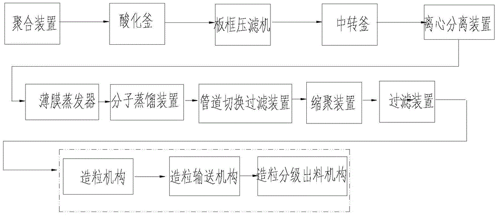
[0028] Such as figure 1 As shown, this embodiment includes a polymerization device, an acidification kettle, a plate and frame filter press, a transfer kettle, a centrifugal separation device, a thin film evaporator, a molecular distillation device, a pipe switching filter device, a polycondensation device, and a filter from front to back according to the process flow. Equipment and granulation system.
[0029] The acidification kettle, the plate and frame filter press, the thin film evaporator and the molecular distillation device are all existing equipment.
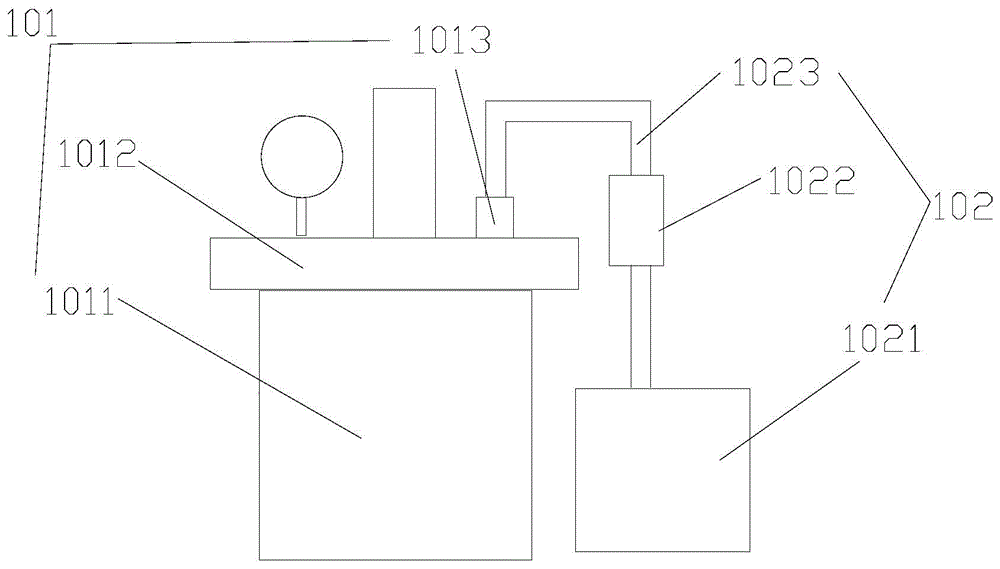
[0030] Such as figure 2 As shown, the polymerization device includes a polymerization tank 101 and a material extraction device 102. The polymerization tank 101 includes a polymerization tank body 1011 and a polymerization tank cover 1012. The polymerization tank cover 1012 is provided with a first feed inlet 1013. The material lifting device 102 includes a material storage tank 1021, a first lifting pump 1022 and a first material guide tube 1023. One end of the first guide tube 1023 is connected to the first inlet 1013, the other end of the first guide tube 1023 is connected to the outlet of the storage tank 1021, and the first lift The pump 1022 is arranged on the first guide tube 1023.
[0031] Such as image 3 As shown, the transfer kettle includes a transfer kettle shell 401 and a contact type automatic alarm system 402, the transfer kettle shell 401 is provided with a second feed port 403, and the contact type automatic alarm device 402 includes a first liquid Position sensor 4021 and alarm system 4022. The first liquid level sensor 402 is suspended in the internal cavity of the transfer kettle shell 401, and the first liquid level sensor 4021 sends out an induction signal to drive the alarm system 4022 to send an alarm signal.
[0032] Such as Figure 4 As shown, the centrifugal separation device includes a centrifuge, a separation tank, and a drain pipe 503. The centrifuge includes a housing 5011, an upper cover 5012, a rotating drum 5013, a light phase weir 5014, and a heavy phase weir 5015. The rotating drum 5013 is arranged at the right center of the housing 5011, the light phase weir 5014 is arranged at the opening area at the top of the rotating drum 5013, and the heavy phase weir 5015 is arranged at the bottom of the upper cover 5012. The shell 5011 is provided with a third inlet 5016, a first water inlet 5017, a light phase outlet 5018, and a heavy phase outlet 5019. The third inlet 5016 and the first water inlet 5017 are located below the light phase outlet 5018 and the heavy phase outlet 5019. The upper cover 5012 is provided with a first drain port 50110, the first drain port 50110 is opposite to the drain pipe 503, and the drain pipe 503 is provided with a second lift pump 504. The separation groove 502 is arranged below the heavy phase outlet 5019, and a baffle 5023 is provided in the separation groove 502, and there is a gap between the bottom of the baffle 5023 and the bottom of the inner wall of the separation groove 502.
[0033] A temperature control device 5021 is provided on the inner wall of the rotating drum 5013. The temperature control device includes a temperature sensor 50211, an electronic heater 50212 and a heating tube 50213. The temperature test range of the temperature sensor 50211 is (50- 100)°C. The temperature range of the water flowing in through the first water inlet 5017 is (85-95) °C, and the baffle 5023 is welded on the side wall of the cavity inside the separation tank 502 to divide the separation tank into the first A cavity 5021 and a second cavity 5022. The gap is (1-5) cm, and the centrifugal separation device 5 further includes a heavy phase discharge pipe 505. A third lift pump 506 is provided on the heavy phase discharge pipe 505. One end is connected to the heavy phase outlet 5019, and the other end of the heavy phase discharge pipe 5023 extends into the first cavity 5021 (may extend into the second cavity 5022). The heavy phase discharge pipe 505 is connected to the heavy phase outlet 5019, and the separation tank is provided with a universal wheel 5024 with a parking device.
[0034] Such as Figure 5-6 As shown, the pipe switching filter device includes a first feed pipe 701, a buffer tank 702, a first multi-way pipe 703, several filter tanks 704, a connecting pipe 705, and a return pipe 706. A fourth lift pump 707 is provided on the return pipe 706. The first multi-way pipe 703 is a three-way pipe, and the three-way pipe is composed of a vertical pipe 7031 and a horizontal pipe 7032. The filter tank 704 includes a first filter tank 7041 and a second filter tank 7042. The vertical pipe 7031 communicates with the discharge port of the buffer tank 702, one end of the horizontal pipe 7032 communicates with the first filter tank 7041 through a first flange 708, and the other end of the horizontal pipe 7031 The second flange 709 communicates with the second filter tank 7042. The inlet of the connecting pipe 705 is connected to the outlet of the first filter tank 7041 through a third flange 7010 (it can also be connected to the outlet of the second filter tank 7042), the connecting pipe 705 The discharge port of is communicated with the return pipe 706 through the fourth flange 7011. A main valve 7033 is also provided on the vertical pipe 7031, and a sub-valve 7034 is provided on both ends of the horizontal pipe 7031. All flanges include a fixed flange 7015, a connecting flange 7016 and fasteners. 7017. The fixed flange 7015 is integrally connected with the connecting flange 7016 through the fastener 7017, and a gasket 7018 is also provided between the fixed flange 7015 and the connecting flange 7016. The surface of the gasket 7018 is coated with a waterproof and anticorrosive layer (not shown in the figure).
[0035] Such as Figure 7 As shown, the polycondensation device includes a polycondensation kettle 801, a dropping device 802, a first tube condenser 803, and a first air duct 804. The first tube condenser 803 is communicated with the inner cavity of the polycondensation reactor 801 through the first air duct 804, and the dripping device 802 includes a liquid storage tank 8021, a liquid guide tube 8022, and a valve 8023. One end of the catheter 8022 is connected to the discharge port of the liquid storage tank 8021, the other end of the catheter 8022 extends into the inner cavity of the polycondensation kettle 801, and the valve 8023 is set in The catheter 8022 is on. The first tube condenser 803 is provided with a first baffle 805, and the first baffle 805 is connected to the condenser tube in the first tube condenser 803; the polycondensation reactor 801 includes polycondensation A kettle body 8011 and a polycondensation kettle cover 8012. The polycondensation kettle body 8011 includes an inner tank 80111 and an outer tank 80112. The outer tank 80112 is provided with a first oil inlet and a first oil outlet. Oil is stored in the cavity between the inner tank body 80111 and the outer tank body 80112, and the kettle cover 8012 is provided with a fourth feed inlet. The polycondensation device 8 further includes an automatic temperature control device 805, which includes a temperature sensor 8051, a circulating oil pipe, a circulating pump 8053, an electronic valve 8054, and an oil storage tank 8055. The temperature sensor 8051 is arranged on the outer tank 80112, and the circulating pump 8053 and the electronic valve 8054 are both arranged on the circulating oil pipe. The oil storage tank 8055 is provided with a second oil inlet and a second oil outlet, and the circulating oil pipe 8055 includes an oil inlet pipe 80551 and an oil outlet pipe 80552. The first oil inlet and the second oil outlet are communicated through the oil inlet pipe 80551, and the first oil outlet and the second oil inlet are communicated through the oil outlet pipe 80552.
[0036] The polycondensation device further includes a heat-insulating protective sleeve 806, and the polycondensation kettle 801 is sleeved in the heat-insulating protective sleeve 806. The circulating pump 8053 is arranged on the oil inlet pipe 80551, and the electronic valve 8054 is arranged on the oil outlet pipe 80552. The circulation pump 8053 is also provided with a power regulator 8058. A non-contact inductive alarm device 807 is provided on the outside of the thermal insulation protective cover 806, and the non-contact inductive alarm device 807 includes an infrared sensor, a processor, and an audible and visual alarm device. The output terminal of the infrared sensor is connected with the input terminal of the processor, and the output terminal of the processor is connected with the input terminal of the sound and light alarm device.
[0037] Such as Figure 8 As shown, the filtering device includes a filter 901, a second feed pipe 902, a first discharge pipe 903, and an oil pipe 904. The second feeding tube 902 includes a second feeding inner tube 9021 and a second feeding outer tube 9022, and the first discharging tube 903 includes a first discharging inner tube 9031 and a first discharging outer tube 9032, Oil is stored in the cavity between the inner tube and the opposite outer tube. The second outer feed pipe 9022 communicates with one end of the oil pipe 904, and the first outer feed pipe 9032 communicates with the other end of the oil pipe 904. Both the first discharge inner tube 9031 and the second feed inner tube 9021 communicate with the inner cavity of the filter 901.
[0038] The filter device further includes a fifth flange 905 and a sixth flange 906. The second feed outer pipe 9022 is connected to one end of the oil pipe 904 through the fifth flange 905, and the first outlet The material outer pipe 9032 is communicated with the other end of the oil pipe 904 through a sixth flange 907. The oil pipe 904 is also provided with an automatic heating device 907, the heating device 907 includes a temperature controller and a heater, and a mobile power interface 908 is also provided on the heater. The temperature controller includes a display screen and a control device, and a USB interface 909 is provided on the control device. The filter 901 includes a protective housing 9011 and a filter assembly 9012 arranged inside the protective housing.
[0039] Such as figure 1 As shown, the granulation system includes a granulation mechanism, a granulation conveying mechanism, and a granulation grading and discharging mechanism from front to back according to the process flow.
[0040] Such as Figure 9-10 As shown, the granulation mechanism includes a distributor and a transmission device, and the distributor includes a granulation drum 100111 and a granulation device 100112. The pelletizing device 100112 includes a pelletizing knife 1001121 and a drive shaft 1001122. The pelletizing knife 1001121 is sleeved in the drive shaft 1001122, and the main body of the drive shaft 1001122 is accommodated in the hollow of the pelletizing cylinder 100111. In the cavity, both ends of the transmission shaft 1001122 extend out of the cavity of the pelletizing cylinder 100111. The bottom of the pelletizing cylinder 100111 is provided with a plurality of regularly arranged material holes 100113, the top of the pelletizing cylinder 100111 is provided with a feeding port 100114, the material hole 100113, the feeding port 100114 and the empty Intercommunications. The transmission device includes a motor 100122, a first gear 100121, a second gear 100123, and a chain 100124. The chain 100124 is sleeved on the first gear 100121 and the second gear 100123. The output shaft of the motor 100122 is The first gear 100121 is connected, and the second gear 100123 is connected with the end of the transmission shaft 1001122.
[0041] The transmission device further includes a tension gear 100125, which is located between the first gear 100122 and the second gear 100123 and is arranged inside the chain 100124. The diameter of the material hole 100113 is 0.8 mm, and a sealing cover 100115 is provided on the outside of the feeding port 100114, and the sealing cover 100115 and the feeding port 100114 are connected by threads. The granulation mechanism further includes two supporting frames 10013, the two supporting frames 10013 are arranged oppositely, the two ends of the granulating cylinder 100111 are arranged on the corresponding supporting frames 10013, and the pelletizing knife 1001121 It is sheathed in the transmission shaft 1001122 in a spiral shape.
[0042] Such as Figure 10-11 As shown, the granulation conveying mechanism includes a conveying device that conveys the particles flowing out through the granulation cylinder 100111. The conveying device includes a driving wheel 100211, a driven wheel 100212, and a cloth plate 100213, and the cloth plate 100213 is sleeved on the driving wheel 100211 and the driven wheel 100212. The conveying device also includes a plurality of arranging plates 100214, the arranging plate 100214 is fixed to the lower cloth plate 100213 perpendicular to the conveying direction of the cloth plate, and ensuring that the length direction of the arranging plate 100214 is the same as that of the cloth plate 100213. The width directions are parallel. Several automatic spraying devices 10022 are also provided on one side of the conveying device. An exhaust gas collection device is also arranged above the conveying device, and the exhaust gas collection device includes a suction device 100231 and a ventilation pipe 100232. The ventilation device 100231 is arranged above the granulation cylinder 100111, one end of the ventilation duct 100232 is connected to the ventilation device 100231, and the other end of the ventilation duct 100231 extends parallel to the length direction of the conveying device to Above the end of the conveying device. Several rows of ventilation holes 100233 are provided at the bottom of the ventilation duct 100232.
[0043] The length of the management plate 100214 is not shorter than the width of the cloth plate 100213, and the bottom of the management plate 100214 is coated with a smooth layer (not shown in the figure). The two ends of the arranging plate 100214 in the length direction are respectively welded with fixed rods (not shown in the figure), and the bottom ends of the fixed rods are fixed on the ground. The automatic spray device 10022 includes a spray head 100221, a heat sensor, a receiver, an electric controller, a water pump 100222, and a water tank 100223. The nozzle 100221 is fixed above the cloth board 100213, and the heat sensor is used to test the heat emitted by the particles distributed on the cloth board 100213. The receiver is used to receive the signal sent by the heat sensor, and the gas-electric controller receives the information sent by the receiver and drives the water pump 100222 to pump water through a motor.
[0044] Such as Figure 12-13 As shown, the granulation, classification and discharge mechanism includes a scraper 10031, a sieving 10032, a discharging funnel 10033, a blower 10034, a separation device 10035, a second discharge pipe 10036, a floc collection device 10037, and a second multi-pass pipe 10038. The knife edge of the scraper 10031 abuts on the cloth board 100213 at the end of the conveying device, the screen 10032 is arranged below the scraper 10031 and is fixed to the open end of the discharging funnel 10033, the discharging The bottom of the funnel 10033 is in direct communication with the second multi-way pipe 10038. The inlet end of the second multi-way pipe 10038 is provided with the blower 10034, the outlet of the multi-port pipe is connected with the inlet of the separation device 10035, and the separation device 10035 is provided with a floc outlet. The bottom of the separating device 10035 is provided with a discharge port. The floc outlet 10035 is communicated with the floc collection device 10037 through the second guide tube 10036. The second discharge pipe 10036 communicates with the discharge port of the separation device 10035. A side knife gate 100310 is provided at the discharge port of the separation device 10035, and a fifth lift pump 100311 is provided on the second guide tube 10036.
[0045] The mesh diameter of the sieving 10032 is (0.6-1.1) mm, and the opening port diameter of the discharging funnel 10033 is equal to the size of the sieving 10032. The side knife gate 100310 includes a baffle plate 1003101 and a knife handle 1003102. One end of the baffle plate 1003101 is hinged with the discharge port of the separating device 10035, and the other end of the baffle plate 1003101 is provided with the Handle 1003102. The fan 10034 is also provided with a power regulating device 100341, and the power regulating device 100341 is a transformer. The granulating, classifying and discharging mechanism further includes two fixed plates 10039, and the two fixed plates 10039 are arranged oppositely on both sides of the end of the conveying device. Each fixed block 10039 is provided with a through groove 100391. The two ends of the scraper 10031 are respectively welded with a screw rod 100311. The screw rod 100311 and the through groove 100391 are connected by sliding, and each screw rod 100311 is also sleeved with two There are two nuts 100312, the nuts are respectively close to the two sides of the corresponding through groove.
[0046] The production method of this embodiment includes the following steps:
[0047] 1) Add vegetable oleic acid, clay, lithium carbonate and water to the polymerization kettle to carry out the polymerization reaction;
[0048] 2) Press the polymerized product into the acidification kettle for acidification;
[0049] 3) Filter the acidified product through a plate and frame filter press to obtain crude dimer acid;
[0050] 4) Press the crude dimer acid into the transfer kettle for temporary storage;
[0051] 5) Feed the crude dimer acid into a centrifugal separation device and mix it with hot water for centrifugal separation;
[0052] 6) The product after centrifugal separation is fed into a thin film evaporator for distillation to remove water vapor;
[0053] 7) Feed the product processed by the thin-film evaporator to the molecular distillation device for separation;
[0054] 8) Feed the refined dimer acid obtained after separation into the pipeline switching filter device into the buffer tank and pre-filter;
[0055] 9) Press the product obtained by the pre-filtration into the polycondensation kettle, while adding ethylenediamine dropwise to perform the polycondensation reaction;
[0056] 10) Filter the product after the polycondensation reaction through a filtering device;
[0057] 11) Feed the filtered product into the granulation system for granulation to obtain the product.
[0058] The vegetable oleic acid used in the step 1) is soybean oil or cotton oil, and the mass ratio of the vegetable oleic acid, the clay, the lithium carbonate, and the water is 100:10:0.5:1.5; The reaction temperature of the polymerization reaction is 230°C, and the reaction time of the polymerization reaction is (3-4) h;
[0059] The acidifying agent used in the step 2) is phosphoric acid, and the mass ratio of the phosphoric acid to the polymerized product is 3:100; the reaction process is: the acidification time is 1 h, and the reaction temperature is (150-180)°C;
[0060] The temperature of adding water in the step 5) is (85-95)°C;
[0061] The vaporization temperature of the step 6) is 160°C;
[0062] The separation temperature in step 7) is 230°C, and the vacuum degree is below 30 Pa;
[0063] In the step 9), the molar ratio of the pre-filtered dimer acid to ethylenediamine is 1:1, and the reaction includes the following stages:
[0064] 8.1) Dimer acid heating stage, the heating temperature is (125-133)℃;
[0065] 8.2) In the dropping stage of ethylenediamine, the dropping time is (25-35) min;
[0066] 8.3) In the stage of heating up and polycondensation, the temperature rises to (190-205)℃;
[0067] 8.4) In the constant temperature stage, the temperature is controlled at (215-225)℃; the constant temperature reaction time is (3-4)h;
[0068] 8.5) In the decompression stage, decompression is performed at 5 mmHg.
[0069] In this embodiment, by adding vegetable oleic acid, clay, lithium carbonate, and water to the polymerization tank 101, the polymerization reaction is performed, and heavy metal ions in the reactants are adsorbed, and then the polymerized product is pressed into the acidification tank for acidification; The frame filter press filters the acidified product to obtain crude dimer acid, which is pressed into the transfer kettle for temporary storage. The crude dimer acid is fed into a centrifugal separation device and mixed with hot water for centrifugal separation. The products after centrifugal separation are sequentially fed to the thin film evaporator and molecular distillation device for distillation and separation to obtain refined Dimer acid. The refined dimer acid obtained after distillation is fed into the pipeline switching filter device into the buffer tank 702 and the pre-filter tank 704; the product obtained by the pre-filtration is pressed into the polycondensation kettle 801, and ethylene diamine is added dropwise to perform the polycondensation reaction; The product after the polycondensation reaction is filtered through the filtering device; the filtered product is fed into the granulation system for granulation to obtain the product.

PUM

no PUM

Description & Claims & Application Information

We can also present the details of the Description, Claims and Application information to help users get a comprehensive understanding of the technical details of the patent, such as background art, summary of invention, brief description of drawings, description of embodiments, and other original content. On the other hand, users can also determine the specific scope of protection of the technology through the list of claims; as well as understand the changes in the life cycle of the technology with the presentation of the patent timeline. Login to view more.

Similar technology patents

Method and device for controlling control operation

InactiveCN103927080Aincrease flexibilitySolve the thumb blind spot
Owner:XIAOMI INC

Self-cleaning control method of cleaning equipment, cleaning equipment and storage medium

InactiveCN111358342Aincrease flexibilityImprove self-cleaning effect
Owner:TIANKE INTELLIGENT TECH CO LTD

Data filter and combination method

InactiveCN101902335Aincrease flexibilitysimple interface
Owner:BEIJING VENUS INFORMATION TECH +1

Classification and recommendation of technical efficacy words

  • increase flexibility

Front illuminated back side contact thin wafer detectors

InactiveUS7057254B2reduce radiation damage susceptibilityincrease flexibility
Owner:OSI OPTOELECTRONICS

Security guarantee method and system for Windows terminals based on auto white list

InactiveCN101650768Aincrease flexibilityImprove the range of adaptation
Owner:SHENZHEN Y& D ELECTRONICS CO LTD

Data processing method and system

InactiveUS20070018986A1increase flexibility
Owner:IBM CORP
Why Eureka
Try Eureka