
Sulfur recovery process and apparatus

A technology of sulfur recovery and process, applied in the direction of sulfur preparation/purification, etc., can solve the problems of sulfur recovery effect not meeting environmental protection requirements, high device safety control requirements, high energy consumption of the device, and achieve long-term stable operation and daily operation Low cost and high desulfurization efficiency

Inactive Publication Date: 2015-10-07
SHANDONG SUNWAY PETROCHEMICAL ENGINEERING CO LTD
View PDF3 Cites 7 Cited by
  • Summary
  • Abstract
  • Description
  • Claims
  • Application Information

AI Technical Summary

Problems solved by technology

[0004] The process is long, and the safety control requirements of the device are high; the regeneration of the alcohol amine solution consumes a large amount of steam, and the incineration of the tail gas consumes a large amount of fuel gas.

Method used


Image

  • Sulfur recovery process and apparatus

Examples


Embodiment 1

[0040] A sulfur recovery process, comprising the following steps:

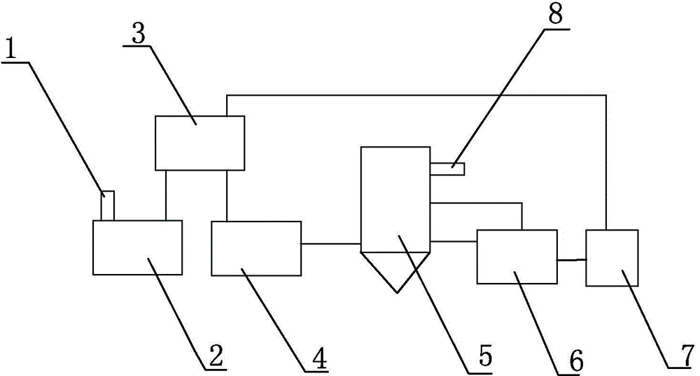
[0041] (1) The acid gas containing hydrogen sulfide enters the sulfur-producing combustion furnace 2 from the acid gas containing hydrogen sulfide inlet 1, and then enters the Claus reaction system 3 for Claus reaction to generate sulfur and sulfur-producing tail gas, wherein the sulfur is recovered to sulfur Recovery tank 7, the tail gas from sulfur production is sent to the tail gas hydrogenation reduction system 4;

[0042] (2) The sulfur-producing tail gas is mixed with hydrogen and sent to the tail gas hydrogenation reduction system 4 for tail gas hydrogenation reduction reaction, and all sulfur-containing media are converted into H 2 S, get H 2 gas of S;

[0043] (3) The H-containing compound obtained in step (2) 2 The gas of S enters H 2 S absorption and solvent oxidation system 5, H 2S absorption and solvent oxidation system 5 contains an absorption liquid, the composition of the absorption liquid...

Embodiment 2

[0047] A sulfur recovery process, comprising the following steps:

[0048] (1) The acid gas containing hydrogen sulfide enters the sulfur-producing combustion furnace 2 from the acid gas containing hydrogen sulfide inlet 1, and then enters the Claus reaction system 3 for Claus reaction to generate sulfur and sulfur-producing tail gas, wherein the sulfur is recovered to sulfur Recovery tank 7, the tail gas from sulfur production is sent to the tail gas hydrogenation reduction system 4;

[0049] (2) The sulfur-producing tail gas is mixed with hydrogen and sent to the tail gas hydrogenation reduction system 4 for tail gas hydrogenation reduction reaction, and all sulfur-containing media are converted into H 2 S, get H 2 gas of S;

[0050] (3) The H-containing compound obtained in step (2) 2 The gas of S enters H 2 S absorption and solvent oxidation system 5, H 2 S absorption and solvent oxidation system 5 contains an absorption liquid, the composition of the absorption liqui...


PUM


Abstract

The invention belongs to the field of sulfur recovery, and particularly relates to a sulfur recovery process. Acidic gas containing hydrogen sulfide has Claus reaction to generate sulfur and sulfur production tail gas, the sulfur is recovered, the sulfur production tail gas is mixed with hydrogen and then is sent to a tail gas hydrogenation reduction system to have hydrogenation reduction reaction, then the mixture enters a H2S absorption and solvent oxidation system, H2S in the gas is oxidized to elemental sulfur, and the purified gas is emptied; finally the sulfur and solvent are separated. The process is a novel sulfur recovery and tail gas treatment process formed by combining the Claus process and a liquid-phase oxidation technology, so that the content of hydrogen sulfide in the discharged gas is minimized, the content of H2S in the treated exhausted gas is reduced to 5ppm or less, the equipment investment is less, the process flow is short, the energy consumption is low, the process flow is safe and reliable, and environmental friendliness can b e realized. The invention also provides an apparatus. The apparatus is simple in structure and easy to implement.

Description

technical field [0001] The invention belongs to the field of sulfur recovery, and in particular relates to a sulfur recovery process and a device thereof. Background technique [0002] my country has been advocating energy conservation and emission reduction work, strictly controlling the emission of sulfur dioxide in the atmosphere. Before 2012, the emission concentration of sulfur dioxide stipulated by the national standard was no higher than 960mg / Nm 3 . At present, the relevant national departments are planning to revise the comprehensive emission standard of air pollutants, requiring the concentration of sulfur dioxide emission from newly built sulfur plants to be less than 400mg / Nm 3 (Specific area discharge concentration is less than 100mg / Nm 3 ). Sinopec actively implements the green and low-carbon development strategy, and regards the reduction of sulfur dioxide emission concentration in the flue gas of the sulfur plant as one of the important indicators for the ...

Claims


Application Information

Patent Timeline
IPC IPC(8): C01B17/04
Inventor 高炬曾翔鹏林彩虹邹光武刘铁军
Owner SHANDONG SUNWAY PETROCHEMICAL ENGINEERING CO LTD
Learn More