Waste gas treatment device

A waste gas treatment device and exhaust port technology, which is applied in the field of waste gas treatment devices, can solve the problems of reduced service life, reduced service life of combustion chambers, and low waste gas treatment efficiency, so as to improve service life, reduce performance requirements, and improve The effect of processing power

Active Publication Date: 2015-10-07
沈阳亿海嘉行电子科技有限公司
View PDF6 Cites 7 Cited by
  • Summary
  • Abstract
  • Description
  • Claims
  • Application Information

AI Technical Summary

Problems solved by technology

[0003] The exhaust gas generated in the semiconductor manufacturing process generally adopts methods such as water washing, combustion, adsorption, and dissociation. However, the method of burning and washing to remove exhaust gas can effectively treat the main waste PFCs in the exhaust gas, and can handle large flow of exhaust gas. At the same time, it can remove various Combustible pollutants have less environmental pollution, but the ashes and high temperature in the combustion chamber are likely to cause fouling on the inner wall of the combustion chamber and reduce the service life of the combustion chamber. Generally, the combustion chamber is cleaned regularly, but often with a scraper Directly use strong removal on the inner wall of the combustion chamber, causing damage to the structure of the combustion chamber, and will still reduce its service life. At the same time, the scraper is generally installed directly in the combustion chamber through the shaft, and the scraper and shaft are required to have the characteristics of fire resistance and high temperature resistance. In addition In addition to combustion, waste gas treatment generally uses water washing or other acid-base liquid washing, but nozzles are generally used to spray out the liquid used for washing or absorption, and the flow of liquid sprayed from the nozzle is limited, resulting in low efficiency of waste gas treatment , and increase the amount of liquid used for washing or absorption, resulting in unnecessary waste of resources

Method used


Image

  • Waste gas treatment device

Examples


Embodiment Construction

[0033] The present invention will be further described in detail below in conjunction with the accompanying drawings, so that those skilled in the art can implement it with reference to the description.

[0034] It should be understood that terms such as "having", "comprising" and "including" as used herein do not entail the presence or addition of one or more other elements or combinations thereof.

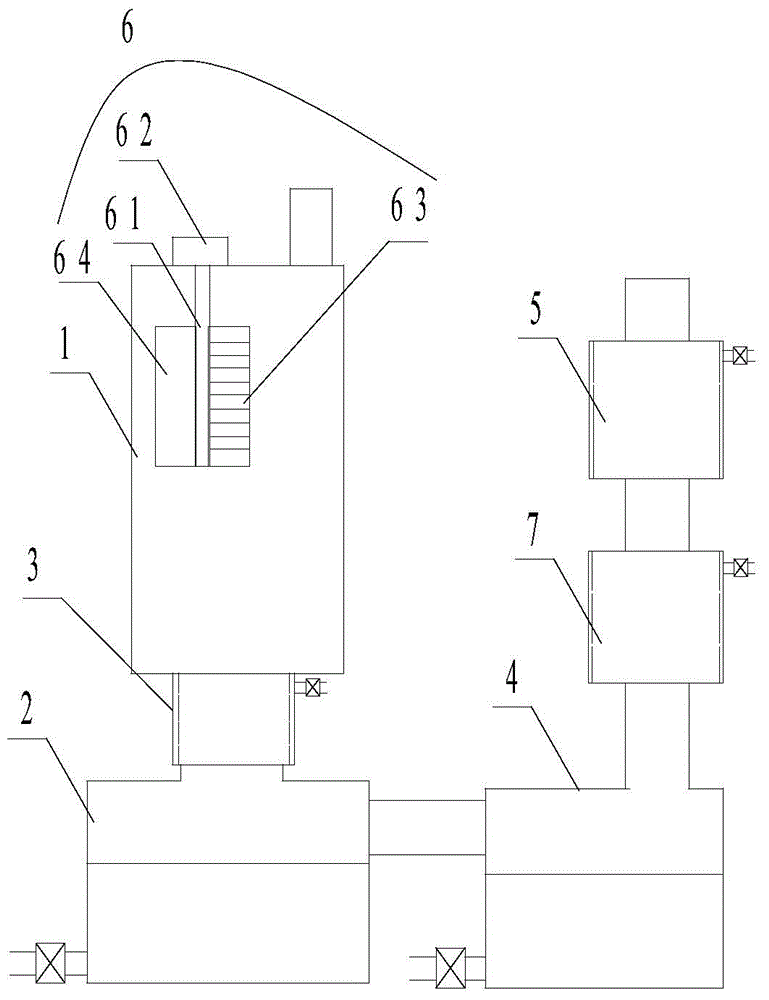
[0035] figure 1 It shows an implementation form according to the present invention, an exhaust gas treatment device, comprising:

[0036] Combustion chamber 1, which is a hollow cylindrical cylinder, the upper part of the combustion chamber 1 is provided with a first air inlet, which communicates with the first air intake pipe, and its lower part is provided with a first exhaust port, wherein the Combustion chamber 1 consists of heat insulation layer, sticky layer and glossy layer from outside to inside;

[0037] The first settling tank 2, which is located below the combustion ...


PUM


Abstract

The invention discloses a waste gas treatment device. The waste gas treatment device comprises a combustion chamber, a first settling basin, a first spray pipe, a second settling basin and a second spray pipe. The combustion chamber is sequentially provided with a heat insulation layer, an adhesive layer and a mill finish layer from outside to inside. The first settling basin is arranged below the combustion chamber. The first spray pipe is connected with the combustion chamber and the first settling basin, and is a hollow cylinder. Containing space is arranged between the inner wall and the outer wall of the first spray pipe. Three layers of round through holes are formed in the inner wall of the first spray pipe in the circumferential direction at intervals. A water inlet hole connected with a control valve is formed in the outer wall of the first spray pipe. The second settling basin is communicated with the first settling basin. One end of the second spray pipe is communicated with the second settling basin, and the other end of the second spray pipe is communicated with the atmosphere. The spray pipes are provided with interlayers, and by means of the round through holes, the contact face of liquid and gas is increased, and the treatment capacity of liquid washing to waste gas is improved. Due to an inner wall cleaning device, the service life of a main shaft is prolonged, and the inner wall of the combustion chamber can be treated by combining the scaling degree of the inner wall.

Description

technical field [0001] The invention relates to an exhaust gas treatment device. More particularly, the present invention relates to an exhaust gas treatment device for treating exhaust gas generated in a semiconductor manufacturing process. Background technique [0002] In the semiconductor manufacturing process, a variety of special gases and a large amount of acid or alkali are used, and a large amount of waste gas is used in different processes of semiconductor manufacturing. These waste gases are collected and treated through the exhaust system to prevent direct discharge to the environment and people. serious health consequences. [0003] The exhaust gas generated in the semiconductor manufacturing process generally adopts methods such as water washing, combustion, adsorption, and dissociation. However, the method of burning and washing to remove exhaust gas can effectively treat the main waste PFCs in the exhaust gas, and can handle large flow of exhaust gas. At the ...

Claims


Application Information

Patent Timeline
Patent Type & Authority Applications(China)
IPC IPC(8): F23G7/06F23J15/04
CPCB08B9/0808F23G7/06F23J15/04
Inventor 黄志强
Owner 沈阳亿海嘉行电子科技有限公司
Why Eureka
Try Eureka