
Antenna oscillator assembly, antenna and communication equipment

An antenna vibrator and component technology, applied in the field of communication, can solve the problems of high cost, large antenna body, and heavy weight, and achieve the effects of compact structure, high integration, and easy integration.

Active Publication Date: 2015-10-07
姜新发
View PDF5 Cites 8 Cited by
  • Summary
  • Abstract
  • Description
  • Claims
  • Application Information

AI Technical Summary

Problems solved by technology

The most widely used today is to add a choke ring around the antenna, which makes the antenna large, heavy and expensive

Method used


Image

  • Antenna oscillator assembly, antenna and communication equipment
  • Antenna oscillator assembly, antenna and communication equipment

Examples


Embodiment Construction

[0028] The principles and features of the present invention are described below in conjunction with the accompanying drawings, and the examples given are only used to explain the present invention, and are not intended to limit the scope of the present invention.

[0029] The invention belongs to the basic antenna unit of broadband and circular polarization. It can be used in the antenna of the global navigation satellite system (GNSS) terminal receiver as the central radiation unit of the antenna. It can also be extended to any antenna that needs to form broadband, circular polarization, and hemispherical beams.

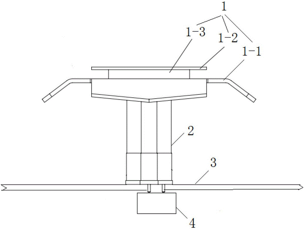
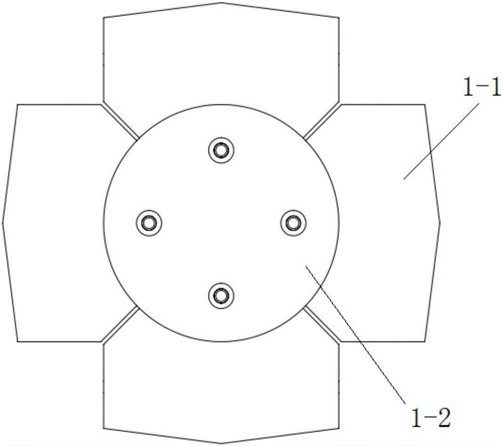
[0030] Such as figure 1 As shown, an antenna dipole assembly includes a cross dipole 1, a support feed assembly 2, a ground plate 3 and a polarization isolation power divider 4; the cross dipole 1 is fixed on the top of the support feed assembly 2, and the The bottom of the support feed assembly 2 is fixed at the center of the ground plate 3, and the polarization ...


PUM


Abstract

The invention relates to an antenna oscillator assembly, an antenna and a piece of communication equipment. The oscillator assembly comprises a cross sector intersecting oscillator, a support feed assembly, a ground plate and a polarization isolation power dividing device. The cross sector intersecting oscillator is fixed on the top of the support feed assembly. The bottom of the support feed assembly is fixed on the center of the ground plate. The polarization isolation power dividing device is arranged on the central position of the ground plate back side. The cross sector intersecting oscillator is connected with the polarization isolation power dividing device through a coaxial supply line inside the support feed assembly. The antenna oscillator assembly which is no longer dependent on microwave dielectric plates solves the multi-frequency wideband circular polarization feed problem. Meanwhile, by forming the cross sector intersecting oscillator and adjusting the height of the cross sector intersecting oscillator away from the ground plate, the antenna oscillator assembly achieves more flexible directional diagram control and optimized circular polarization characteristics. By means of the polarization isolation power dividing device, the antenna oscillator assembly can make de-rotation multipath signals suppressed. The antenna oscillator assembly which has the characteristics of wideband, low consumption and high efficiency can make the volume, the weight and the cost of the antenna obviously reduced.

Description

technical field [0001] The invention relates to the technical field of communication, in particular to an antenna dipole assembly, an antenna and communication equipment. Background technique [0002] (1) Technological progress of multi-frequency broadband: The bandwidth of the receiver system is first determined by the bandwidth of the antenna unit. At the beginning of GPS application, for GPS-L1 single-frequency mode, a single-layer microstrip patch antenna is used, and its bandwidth of only 1% can meet the application requirements; subsequently, in order to improve positioning accuracy, differential GPS is used, and dual-frequency GPS is used -L1 and GPS-L2, the double-layer microstrip antennas work in the L1 and L2 frequency bands respectively, and the bandwidth is easy to reach; in today's GNSS era where multiple satellites coexist, the antenna is required to cover the entire navigation frequency band, from 1.1 to 1.7GHz. The original microstrip and four-arm helical an...

Claims


Application Information

Patent Timeline
Patent Type & Authority Applications(China)
IPC IPC(8): H01Q1/12H01Q1/36H01Q1/22H01Q5/00
Inventor 叶云裳
Owner 姜新发
Learn More