Forward-flyback topology switched mode power supply

A switching mode power supply and current technology, which is applied in the direction of electronic switches, electrical components, and adjustment of electrical variables, can solve the problems of increasing the number of components and manufacturing costs, and achieve the effect of reducing resistance loss and capacitive coupling loss

Active Publication Date: 2015-10-14
TELEFON AB LM ERICSSON (PUBL)
View PDF6 Cites 3 Cited by
  • Summary
  • Abstract
  • Description
  • Claims
  • Application Information

AI Technical Summary

Problems solved by technology

All this increases component count and manufacturing cost

Method used


Image

  • Forward-flyback topology switched mode power supply
  • Forward-flyback topology switched mode power supply
  • Forward-flyback topology switched mode power supply

Examples


Embodiment 1

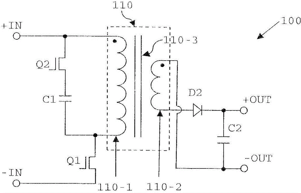
[0044] Figure 4A A switched mode power supply according to a first embodiment of the invention is shown. Figure 4A The SMPS 400 shown in has a forward-flyback topology converter with an active clamp on the primary side. For example, the SMPS of this embodiment can be used to enable a radio frequency power amplifier (RFPA) to deliver an output voltage of 10-32V or 17-32V.

[0045] More specifically, the flyback converter 400 includes a flyback transformer 410 having a primary winding 410-1 and a secondary winding 410-2 with Turns ratio N=n p / n s Wound transformer core 410-3, where n p and n s are the turns of the primary winding 410-1 and the secondary winding 410-2, respectively. Transformer core 410-3 may be formed from any suitable material (including, for example, powdered iron or other material with high magnetic permeability), and may be shaped such that transformer 110-3 has The gap (for example, an air gap) of the magnetizing energy provided.

[0046] The pr...

Embodiment 2

[0063] will now refer to Figure 7A and Figure 7B A switched mode power supply according to a second embodiment of the present invention will be described.

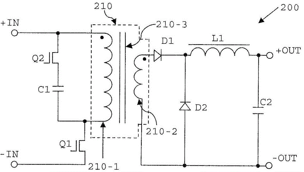
[0064] Figure 7A The SMPS 500 shown in FIG. 2 differs from the SMPS 400 of the first embodiment only in that the cathodes of diodes D1 and D2 are connected to opposite ends of inductor L1. Therefore, with Figure 4A Contrary to the SMPS 400, the cathode of the diode D2 is connected to the output terminal +OUT of the SMPS 500 instead of being indirectly connected to +OUT through the inductor L1. In this alternate embodiment, power is delivered to the output of the SMPS through Q4 and D2 (while bypassing choke L1) during the flyback phase, and power is delivered to the output of the SMPS via choke L1 during the forward phase. output. Routing current on the secondary side to bypass choke L1 can provide the advantage of reducing losses during the flyback phase.

[0065] The switched-mode power supplies of the first an...

Embodiment 3

[0067] will now refer to Figure 8A and 8B A switched mode power supply according to a third embodiment of the present invention will be described.

[0068] Figure 8A The SMPS 600 shown in , differs from the SMPS 400 of the first embodiment only in that it is provided in the form of synchronous rectifiers Q5 and Q6 instead of the passive rectifiers of SMPS 400 (i.e., diodes D1 and D2). High-side rectifier on the secondary side. The switched-mode power supplies of the first and third embodiments are otherwise identical, and repeated descriptions will be omitted for simplicity.

[0069] The SMPS 600 of the third embodiment operates in the same manner as the first embodiment, except for the above-mentioned fully synchronous rectification provided on the secondary side, as Figure 8B The trajectories (a) to (e) in are shown. More specifically, a control signal generator (not shown) may be provided on the primary or secondary side of the transformer 410 for generating signals...


PUM


Abstract

A switched mode power supply (400), comprising a transformer (410) having a primary winding (410-1), a transformer core (410-3) configured to store energy transferred thereto from the primary winding (410-1) during operation, and a secondary winding (410-2) having a first terminal (Tl) and a second terminal (T2). The switched mode power supply also has a primary side circuit (Q1, Q2, C1) arranged to generate voltage pulses and thereby to drive the primary winding (410-1) of the transformer (410), and a secondary side circuit comprising a rectification circuit connected to the secondary winding (410-2) at the first and second terminals (Tl, T2). The rectification circuit is arranged such that during a forward phase of operation of the switched mode power supply, in which the primary winding (410-1) is driven by the primary side circuit to magnetise, and store energy in, the transformer core (410-3), a current induced to flow in the secondary winding (410 -2) from the second terminal (T2) to the first terminal (Tl) is output by the rectification circuit. The rectification circuit is further arranged such that during a flyback phase of operation of the switched mode power supply, in which the magnetisation of the transformer core (410-3) is reset, a current induced to flow in the secondary winding from the first terminal (Tl) to the second terminal (T2) of the secondary winding (410 -2) is output by the rectification circuit so that energy stored in the transformer (410) during the forward phase of operation is output by the rectification circuit.

Description

technical field [0001] The present invention relates generally to the field of switch mode power supplies (sometimes referred to as switch mode power supplies or switching mode power supplies), and more particularly to switch mode power supplies of forward flyback circuit topology. Background technique [0002] Due to their small size and weight and high efficiency, a switched-mode power supply (SMPS) is a well-known type of power converter with a wide range of applications, for example in personal computers and portable electronic devices such as cell phones. SMPSs achieve these advantages by switching one or more switching elements, such as power MOSFETs, at high frequencies (typically tens to hundreds of kHz), where the frequency and duty cycle of the switches are adjusted using a feedback signal to convert the input voltage to the desired output voltage. An SMPS can be in the form of a rectifier (AC / DC converter), a DC / DC converter, a frequency converter (AC / AC) or an i...

Claims


Application Information

Patent Timeline
Patent Type & Authority Applications(China)
IPC IPC(8): H02M3/335
CPCH02M3/33538H02M3/33592Y02B70/1475H02M1/08H02M3/33576H03K2017/307Y02B70/10H02M3/33546
Inventor O·珀森M·阿佩尔贝格M·卡尔森
Owner TELEFON AB LM ERICSSON (PUBL)
Why Eureka
Try Eureka