
A sampling device for a hematology analyzer

A technology of a blood cell analyzer and a sample injection device, which is applied in the directions of analyzing materials and instruments, can solve the problems that the guiding accuracy of the linear bearing is difficult to meet the accurate positioning, the rigidity of the guiding shaft is insufficient, and the maintenance is inconvenient. The effect of reducing processing difficulty and cost

Active Publication Date: 2017-06-06
ZHONGSHAN CHUANGYI BIOCHEM ENG
View PDF6 Cites 0 Cited by
  • Summary
  • Abstract
  • Description
  • Claims
  • Application Information

AI Technical Summary

Problems solved by technology

[0003] The existing blood cell analyzer sampling device is realized by the motor driving the belt to move back and forth. Its linear motion guiding mechanism is a combination of linear bearings and linear guide shafts. In medical equipment with a high degree of automation, the guiding accuracy of linear bearings has become difficult. To meet the requirements of accurate positioning, due to the compact structure and the long guide shaft, there are two problems: 1. Insufficient rigidity of the guide shaft leads to reduced guide accuracy
2. Although the guide shafts arranged in parallel can improve the accuracy, they have high requirements for assembly and inconvenient maintenance

Method used


Image

  • A sampling device for a hematology analyzer
  • A sampling device for a hematology analyzer
  • A sampling device for a hematology analyzer

Examples


Embodiment 1

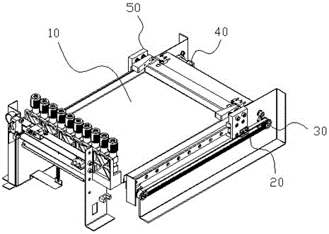
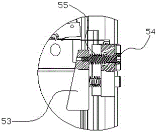
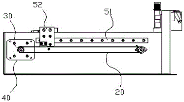
[0022] Such as Figure 1-5 As shown, this embodiment discloses a sample introduction device for a blood cell analyzer, which includes a test tube sample rack loading tray 10, a timing belt 20, a timing belt wheel 30 that drives the timing belt 20 to reciprocate, and a motor that drives the timing belt wheel 30 to rotate. 40 and guide mechanism 50. The timing belt 20, the timing belt wheel 30, and the motor 40 are combined to form the driving part of the sampling device.

[0023] Such as Figure 1-2 As shown, the guide mechanism 50 includes a linear slide rail 51 parallel to the timing belt 20 and a slider 52 that can slide on the linear slide rail 51. The slider 52 is fixedly connected to the timing belt 20 and is driven by a motor 40 to move. There are two linear slide rails 51, and the loading tray 10 is arranged between the two slide rails 51 for loading a sample rack with sample tubes. A push block 53 for pushing the sample rack is riveted on the slider 52, and the push blo...

Embodiment 2

[0029] Such as Image 6 As shown, this embodiment provides an automatic sample tube transfer system for a blood cell analyzer, including the above-mentioned sample injection device, and further includes a sample dragging device 80 and a mixing device 90; the dragging device 80 is used to transport the sample injection device to The test tube sample rack at the designated position is transported to the mixing device 90, the mixing device 90 is shaken for a predetermined number of times or for a period of time, and then the sample dragging device 80 sends the test tube sample rack out of the mixing device 90.


PUM


Abstract

The invention relates to the technical field of medical and health equipment, in particular to a sample feeding device for a blood cell analyzer, which includes a test tube sample rack loading tray, a timing belt, a timing pulley that drives the reciprocating motion of the timing belt, and a timing pulley that drives the timing belt A rotating motor and a guide mechanism; the guide mechanism includes a linear slide rail parallel to the synchronous belt and a slide block that can slide on the linear slide rail; the slide block is fixedly connected to the synchronous belt, and is controlled by The motor is driven to move; it also includes a push block fixed on the slide block and moves reciprocatingly with the synchronous belt; the test tube sample rack is pushed by the push block along the guide mechanism to move the test tube The test tube sample rack is transported to the designated position. The present invention adopts the linear guide rail instead of the existing linear bearing as the guiding transmission mechanism, which has large load, stronger stability and sufficient rigidity.

Description

Technical field [0001] The invention relates to the technical field of medical and health equipment, and in particular to a sampling device of a blood cell analyzer. Background technique [0002] The blood cell analyzer is one of the most widely used instruments in hospital clinical testing. With the rapid development of computer technology, blood cell analysis has also shifted from three groups to five groups, from two-dimensional space to three-dimensional space, and we have also noticed modern blood cells. The five-classification technology of the analyzer uses the same technology as the most advanced flow cytometer today, such as scattered light detection technology, sheath flow technology, laser technology and so on. [0003] The existing blood cell analyzer sampling device is realized by the motor driving the belt to move back and forth. Its linear motion guiding mechanism is a matching of linear bearings and linear guide shafts. In highly automated medical equipment, the gui...

Claims


Application Information

Patent Timeline
Patent Type & Authority Patents(China)
IPC IPC(8): G01N35/10
Inventor 蒋正国王菁菁
Owner ZHONGSHAN CHUANGYI BIOCHEM ENG
Learn More