Fuel heater

A technology of fuel heater and radiator cover, which is applied to fuel heat treatment devices, machines/engines, combustion air/combustion-air treatment, etc., can solve the problems of low combustion efficiency, air pollution, high noise, etc., and achieve high combustion power , the effect of reducing pollution and low fuel consumption

Inactive Publication Date: 2015-10-28
宁波中创机电有限公司
View PDF5 Cites 2 Cited by
  • Summary
  • Abstract
  • Description
  • Claims
  • Application Information

AI Technical Summary

Problems solved by technology

[0002] In winter, due to the low temperature, the power system of the car often suffers from frost, icing and condensation in the mailbox and oil pipelines and cannot be started. As an independent heating device, the fuel heater is often used in freight cars , passenger cars, construction machinery and other transport machinery in low temperature environment heating, thawing, defrosting, cold start, etc., the current common fuel heaters on the market can be divided into oil throwing heaters, electrospray heating There are three kinds of fuel heaters and volatile ignition liquid heaters, and these three kinds of fuel heaters are not easy to ignite after actual use, the ignition time is long, the fuel consumption is large, the combustion efficiency is low, the noise is large, and they will release during the ignition process. A large amount of harmful gases such as carbon dioxide cannot be discharged well, causing air pollution and potential harm to the human body

Method used


Image

  • Fuel heater
  • Fuel heater

Examples


Embodiment Construction

[0031] The present invention will be described in detail below in conjunction with the accompanying drawings.

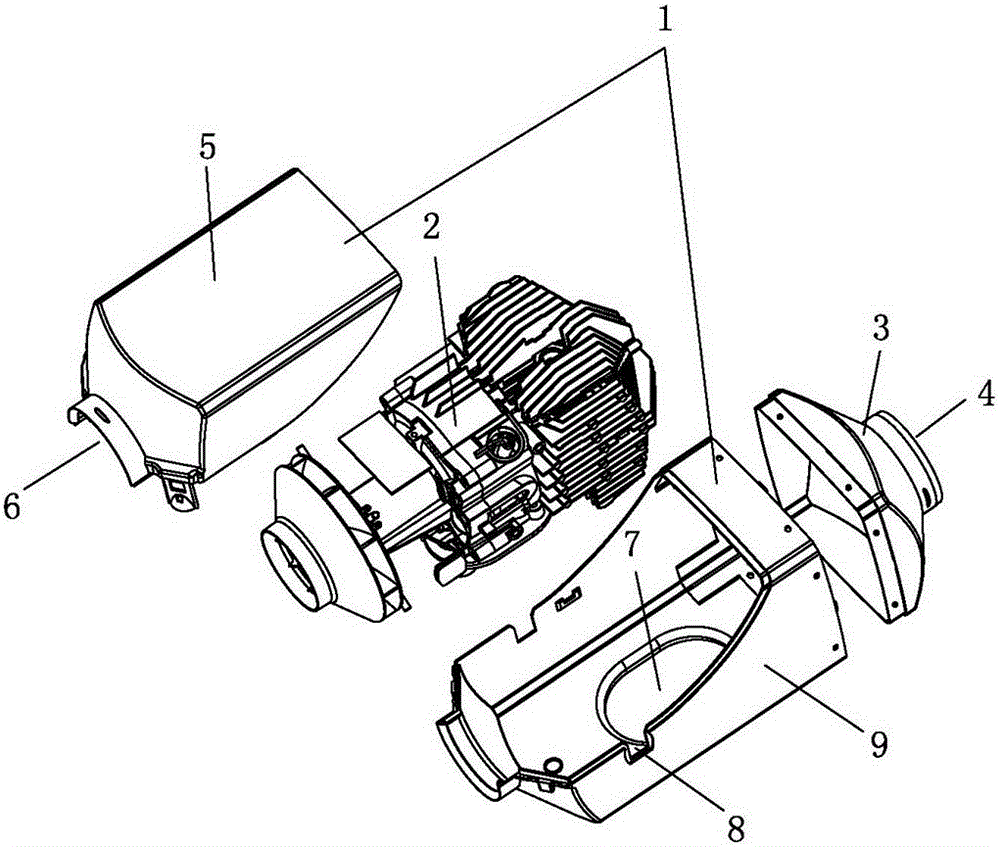
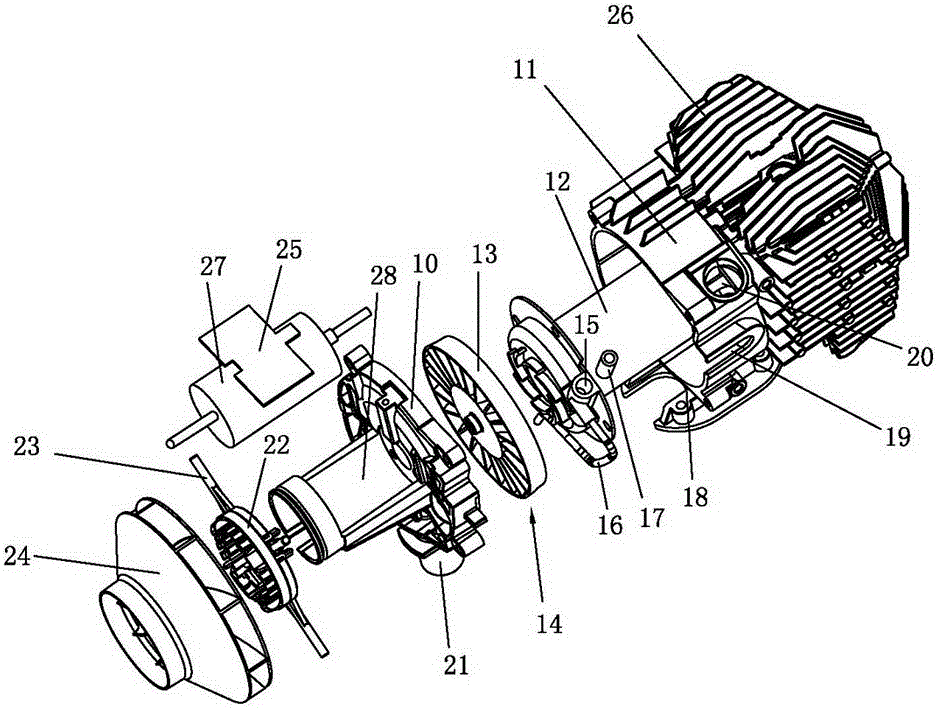
[0032] Such as figure 1 and figure 2 As shown, a fuel heater includes a ventilation box 1 and a heating device assembly 2. The ventilation box 1 is composed of an upper box 5 and a lower box 9. The right end of the ventilation box 1 is buckled. There is a cover 3, the right end of the cover 3 is provided with an air outlet 4, the left end of the ventilation box 1 is provided with an air inlet 6, the bottom of the ventilation box 1 is provided with a ventilation hole 7, and the ventilation box 1 1 There is a power cord slot 8 in the middle of both sides. The ventilation box 1 is provided with a heating device assembly 2. The heating device assembly 2 includes a motor mounting frame 28, and a motor is installed in the motor mounting frame 28. 27. The right end of the motor mounting frame 28 is provided with a flange 10, and the right end of the flange 10 is screwed ...


PUM


Abstract

The invention relates to a fuel heater which comprises a ventilator box body and a heating device assembly, wherein the heating device assembly comprises a motor mounting frame; a motor is arranged in the motor mounting frame; a flange plate is arranged at the right end of the motor mounting frame; a heat dissipation hood is in screwed connection with the right end of the flange plate; a heating tube is arranged in the heat dissipation hood; an atomizing chamber is formed after the left end of the heating tube is in sealed and screwed connection with the middle part of the flange plate; an atomizing fan is arranged in the atomizing chamber; an ignition hole is formed in the left end of the heating tube; an oil inlet tube is arranged in the middle of the ignition hole; an air inlet fan is arranged at the left part of the motor mounting frame, namely an air inlet hole; through rapid atomizing ignition of diesel oil in the atomizing chamber, heat is supplied to the heating rube, dissipated by the heat dissipation hood to the interior of the ventilator box body, and pushed by the air inlet fan in the air inlet hole out of an air outlet, so that the advantages of high power, low noise, low oil consumption and high heat can be realized; moreover, carbon dioxide and other harmful gases in the heat dissipation hood can be exhausted through an exhaust pipe, so that the pollution is reduced.

Description

technical field [0001] The invention relates to the technical field of vehicle heating equipment, in particular to a fuel heater. Background technique [0002] In winter, due to the low temperature, the power system of the car often suffers from frost, icing and condensation in the mailbox and oil pipelines and cannot be started. As an independent heating device, the fuel heater is often used in freight cars , passenger cars, construction machinery and other transport machinery in low temperature environment heating, thawing, defrosting, cold start, etc., the current common fuel heaters on the market can be divided into oil throwing heaters, electrospray heating There are three kinds of fuel heaters and volatile ignition liquid heaters, and these three kinds of fuel heaters are not easy to ignite after actual use, the ignition time is long, the fuel consumption is large, the combustion efficiency is low, the noise is large, and they will release during the ignition process....

Claims


Application Information

Patent Timeline
Patent Type & Authority Applications(China)
IPC IPC(8): F02M31/16F02N19/04
Inventor 岑宏华
Owner 宁波中创机电有限公司
Why Eureka
Try Eureka