
Chip-type Ka-frequency band wide-angle scanning satellite communication antenna
A wide-angle scanning and satellite communication technology, which is applied in the field of chip Ka-band wide-angle scanning satellite communication antennas, can solve the problems of being unable to adapt to small, mobile and flexible carriers, and high profile, so as to achieve over-the-horizon measurement and control and communication requirements, reduce Manufacturing cost, effects of increased system integration and utilization
Patent Information
- Authority / Receiving Office
- CN · China
- Patent Type
- Applications(China)
- Current Assignee / Owner
- Publication Date
- 2015-11-04
Smart Images
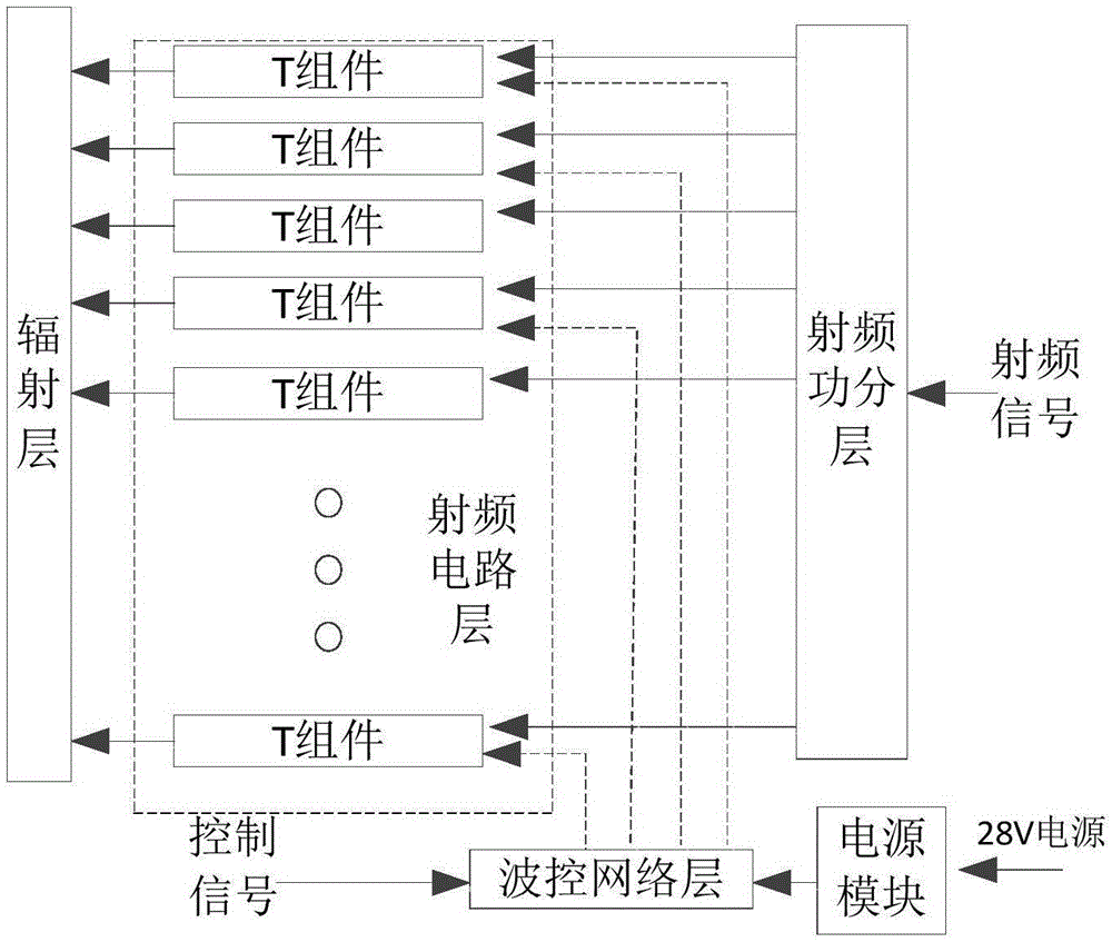
Figure 1 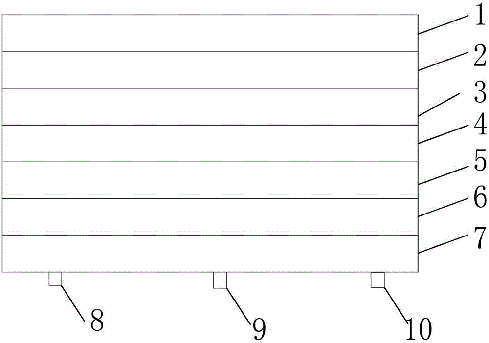
Figure 2 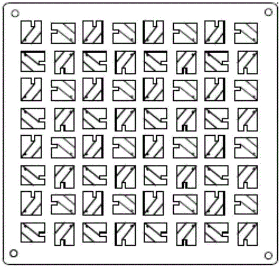
Figure 3
Abstract
Description
technical field
[0001] The invention relates to a mobile satellite communication technology, in particular to a chip type Ka frequency band wide-angle scanning satellite communication antenna. Background technique
[0002] Mobile service satellite communication refers to the business of ships, aircraft, missiles, vehicles, etc. using satellites for communication, including communication between ships, aircraft, or between them and fixed stations. With the development of satellite technology and microwave technology, the miniaturization and light weight of satellite mobile communication system terminals have become possible, and the terminal applications mainly involve antenna and radio frequency module miniaturization technology and antenna and radio frequency circuit integration technology.
[0003] Antenna is an essential component of any radio system. It undertakes the functions of transmitting and receiving electromagnetic waves. Without it, any wireless communication fu...
Examples
Embodiment Construction
[0036] The following is a detailed description of the embodiments of the present invention. This embodiment is implemented on the premise of the technical solution of the present invention, and detailed implementation methods and specific operating procedures are provided, but the protection scope of the present invention is not limited to the following implementation example.
[0037] Such as figure 1 with figure 2 As shown, this embodiment includes a radiation layer 1, a correction network layer 2, a radio frequency circuit layer 3, an environmental control layer 4, a power distribution layer 5, a radio frequency signal power layer 6 and a wave control network layer 7 arranged in sequence from top to bottom. ;
[0038] The radiation layer 1 is respectively connected to the correction network layer 2 and the radio frequency circuit layer 3, and is used to radiate the radio frequency signal of the radio frequency circuit layer 3 to space;
[0039] The correction network la...