A subway energy feedback device

An energy feedback, subway technology, applied in output power conversion devices, power management, transportation and packaging, etc., can solve the problem that the three-phase inverter AC output cannot be directly connected in parallel, the switching ripple filtering effect is limited, and harmonic pollution. and other problems to achieve the effect of ensuring achievability, high reliability and good waveform quality

Active Publication Date: 2018-05-18
NANJING APAITEK TECH
View PDF8 Cites 0 Cited by
  • Summary
  • Abstract
  • Description
  • Claims
  • Application Information

AI Technical Summary

Problems solved by technology

However, in order to avoid short circuit or circulating current between the two three-phase inverters, the AC outputs of the two three-phase inverters cannot be directly connected in parallel, but can only be connected to two independent windings on the low-voltage side of the step-up transformer. Reflected on the side of the step-up transformer
In this way, the grid-connected output filter of the inverter is only a single-inductance filter including the leakage inductance of the transformer, and the switching ripple filtering effect of the single-inductance filter is limited, and the switching ripple will pollute the power grid
[0006] In summary, this kind of subway energy feedback device using single-inductor filtering will cause serious harmonic pollution problems

Method used


Image

  • A subway energy feedback device

Examples


Embodiment Construction

[0022] In order to make the object, technical solution and advantages of the present invention clearer, the present invention will be further described in detail below in conjunction with the accompanying drawings and embodiments. It should be understood that the specific embodiments described here are only used to explain the present invention, not to limit the present invention. In addition, the technical features involved in the various embodiments of the present invention described below can be combined with each other as long as they do not constitute a conflict with each other.

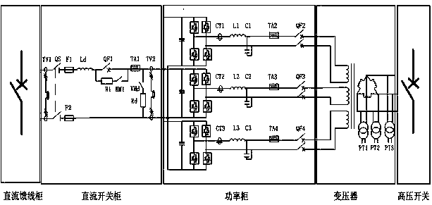
[0023] A subway energy feedback device, including: a DC switch cabinet, a power cabinet electrically connected to the DC switch cabinet through copper bars, and a transformer. Low-voltage alternating current, the low-voltage alternating current is boosted by a transformer into medium-voltage alternating current and fed into the medium-voltage grid. Two-current Hall sensors, AC circuit breakers,...


PUM


Abstract

Disclosed in the invention is a subway energy feedback apparatus comprising a direct-current switch cabinet, a power cabinet, and a transformer. The power cabinet and the transformer are electrically connected with the direct-current switch cabinet. The power cabinet consists of a three-phase H-bridge inverter, alternating-current current transformers, an inverter side filter inductor, an alternating-current filter capacitor, second current hall sensors, and alternating-current circuit breakers. Input terminals of all phases of the three-phase H-bridge inverter are respectively connected with an output terminal of the direct-current switch cabinet; output terminals of all phases are respectively connected with input terminals of the respective alternating-current current transformer; and output terminals of all alternating-current current transformers are connected with corresponding filter input terminals; all filter output terminals are connected with corresponding current hall sensor input terminals; and the current hall sensor output terminals are connected with alternating-current circuit breakers output terminals. A direct current inputted into the power cabinet by the direct-current switch cabinet is processed by three-phase H-bridge single-polarity double-frequency inversion with the switching frequency of f; and then a three-phase pulse alternating current with an equivalent switching frequency of 2f is outputted. The pulse alternating current is processed by an LCL filter to obtain a three-phase sinusoidal low-voltage alternating current; and the low-voltage alternating current is processed by boosting by the transformer to obtain a medium-voltage sinusoidal alternating current that is then fed into a medium-voltage power grid. With the apparatus, the harmonic pollution can be effectively reduced; the reliability is high; the size is small; and the cost is low.

Description

technical field [0001] The invention relates to the technical field of urban rail transit power supply systems, in particular to a subway energy feedback device. Background technique [0002] In recent years, my country's urban rail transit has developed very rapidly. The existing subway traction power supply method uses a diode rectifier unit to rectify 35 / 33kV medium-voltage AC power into 1500V DC, and supplies power to the traction motor on the subway train through the DC catenary. However, this power supply method can only realize the one-way power flow of electric energy from the grid to the motor, and the motor works in the generator state during the braking process, and the mechanical energy of the train is converted into electric energy. In order to ensure that the DC catenary voltage is within the safe range, the electric energy generated by train braking is basically absorbed by the resistance power consumption method, which causes a great waste of electric energy....

Claims


Application Information

Patent Timeline
Patent Type & Authority Patents(China)
IPC IPC(8): H02M7/483H02M7/5387H02M1/12H02M5/12H02J5/00B60L7/16
CPCY02T10/72
Inventor 仇志凌李锦胡磊磊朱铮平花跃学刘定坤许忠元张勇芮国强万里强张明葛文海
Owner NANJING APAITEK TECH
Why Eureka
Try Eureka