Current measuring device

A technology of current measuring device and signal processing circuit, which is applied in the direction of measuring device, only measuring current, measuring electrical variables, etc., can solve the problems of proportional error temperature characteristics, etc., and achieve the effect of reducing the fluctuation range and stabilizing output characteristics

Active Publication Date: 2015-11-04
NAMIKI PRECISION JEWEL CO LTD
View PDF10 Cites 8 Cited by
  • Summary
  • Abstract
  • Description
  • Claims
  • Application Information

AI Technical Summary

Problems solved by technology

[0004] However, the Faraday rotation angle of a Faraday rotator used in a current measuring device has a characteristic (temperature characteristic) depending on the ambient temperatu

Method used


Image

  • Current measuring device
  • Current measuring device
  • Current measuring device

Examples


Embodiment 1

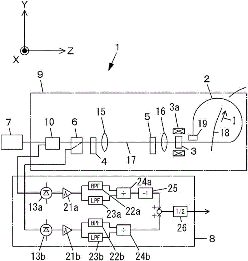
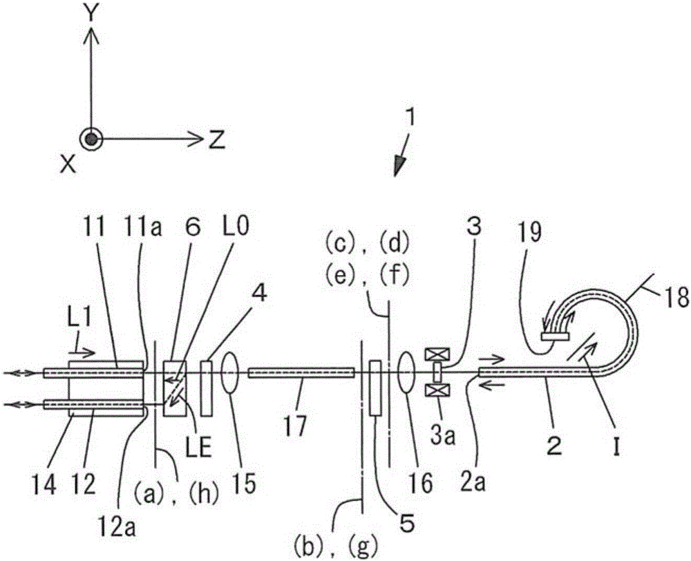
[0158] as figure 2 The Faraday rotator 3, indicated for use in opto-isolators, uses features such as Figure 14 An example of a magnetic garnet showing the temperature characteristics of the Faraday rotation angle. A Faraday rotator with a Faraday rotation angle set to 22.5°+1.0° at a temperature of 23° C. was used. That is, α=1.0° is set, and the total Faraday rotation angle at the time of magnetic saturation when the circularly polarized lights LC1 and LC2 transmit back and forth is set to 47.0°. The temperature-proportional error characteristics in the measured value of the measured current I output from the signal processing circuit of the current measuring device 1 having such a Faraday rotator 3 are shown in Table 1 and Figure 24 . In addition, the Faraday rotation angle in Table 1 refers to the total Faraday rotation angle at the time of magnetic saturation when the circularly polarized lights LC1 and LC2 transmit back and forth. In addition, the proportional erro...

Embodiment 2

[0163] The temperature dependence of the rotation angle of the reciprocating magnetic garnet was expressed by the following quadratic formula (mathematical formula 1), and the minimum value of the variation width of the proportional error of the phase coefficient a and the coefficient b was calculated. In addition, the coefficient c is set such that the proportional error fluctuation range takes the minimum value. Table 2 shows the relationship between the variation range of the proportional error and coefficient a and coefficient b. In addition, as shown in Table 2, the relationship between the Faraday rotation angle adjustment part α° and the coefficient a and coefficient b at a temperature of 23° C. when the proportional error fluctuation range is the minimum value is shown in Table 3.

[0164] Mathematical formula 1

[0165] θF=a·T2+b·T+c In addition, T: temperature [°C]

[0166] Table 2

[0167]

[0168] table 3

[0169]

[0170] Table 2 and Table 3 have a point...

Embodiment 3

[0180] Based on the research results in Table 2, the development of a magnetic garnet for reducing the proportional error by a Faraday rotator was carried out. As a result, a magnetic garnet having a temperature dependence shown in Mathematical Formula 3 below was obtained. The Faraday rotation angle at a temperature of 23° C. is 24.22°, that is, α=1.72°. The temperature dependence of the obtained magnetic garnet is shown in Figure 29 .

[0181] Mathematical formula 3

[0182] θF=-1.64.·10-4·T2-0.0185·T+48.95 In addition, T: temperature [°C]

[0183]The total Faraday rotation angle at the time of magnetic saturation when circularly polarized light LC1 and LC2 are reciprocally transmitted is 48.44°. The temperature-proportional error characteristics in the measured value of the measured current I output from the signal processing circuit of the current measuring device 1 having such a Faraday rotator 3 are shown in Table 5 and Figure 30 .

[0184] table 5

[0185]

...


PUM


Abstract

Provided is a current measuring device such that it is possible to reliably keep the fluctuation range for the ratio error in output to within a range of ±0.5% and such that assembly thereof can be simplified. The current measuring device is configured to include at least a light entrance and exit, an optical fiber for a sensor, a Faraday rotator, a first 1/4 wavelength plate, a second 1/4 wavelength plate, a polarization separator, a light source, and a signal processing circuit comprising a photoelectric conversion element. The optical fiber for a sensor has birefringence and comprises one end into which two circularly polarized light beams having different directions of rotation enter and another end that reflects the circularly polarized light beams that have entered. In addition, the phase difference of two linearly polarized light beams in the round-trip light path between the two 1/4 wavelength plates is compensated, and the Faraday rotational angle when the Faraday rotator is magnetically saturated is set to 22.5°+α° so that the fluctuation range for the ratio error in the measured value of the current to be measured is set to be in the range of ±0.5%. In addition, the crystal axes on the optical faces of the two 1/4 wavelength plates are set to be perpendicular or are set to be in the same direction.

Description

technical field [0001] The present invention relates to a current measuring device utilizing the Faraday effect, and relates to a reflection type current measuring device in which light is incident on one end side of an optical fiber for a sensor and reflected on the other end side. Background technique [0002] There is known a current measuring device that utilizes the Faraday effect of an optical fiber and has various advantages such as small size, flexibility, resistance to electromagnetic noise, long-distance signal transmission, and voltage resistance. As an example of such a current measuring device, Patent Document 1 discloses a reflection type current measuring device utilizing the Faraday effect in which the plane of polarization of light is rotated by the action of a magnetic field. [0003] This current measuring device is a reflection type current measuring device in which a lead glass fiber is used as a sensor fiber and a reflection mirror is arranged at the ot...

Claims


Application Information

Patent Timeline
IPC IPC(8): G01R15/24
CPCG01R15/246G01R19/0092
Inventor 今野良博佐佐木胜
Owner NAMIKI PRECISION JEWEL CO LTD
Why Eureka
Try Eureka