Polishing device capable of controlling horizontal contact pressure

A technology of polishing device and contact pressure, which is applied in the direction of grinding/polishing equipment, optical surface grinder, grinding machine tool parts, etc. It can solve the problems affecting the local modification ability and surface accuracy of polishing tools, and realize the distribution of removal amount , Improve stability, improve the effect of surface shape accuracy

Inactive Publication Date: 2015-11-11
HARBIN INST OF TECH
View PDF7 Cites 7 Cited by
  • Summary
  • Abstract
  • Description
  • Claims
  • Application Information

AI Technical Summary

Problems solved by technology

[0005] The present invention solves the problem that the existing controllable contact pressure polishing tool has the problem of affecting the local modification ability and surface shape accuracy of the polishing tool due to the change of the contact pressure and the range of the contact area due to the change of the geometric characteristics of the workpiece surface during the processing process, and then Provide a polishing device with controllable horizontal contact pressure

Method used


Image

  • Polishing device capable of controlling horizontal contact pressure

Examples


specific Embodiment approach 1

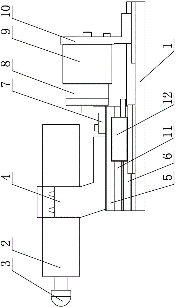
[0013] Specific implementation mode one: as figure 1 As shown, the polishing device with controllable horizontal contact pressure in this embodiment includes a polishing device base 1, a polishing spindle 2, a polishing head 3, a spindle mounting seat 4, a linear slide slide 5, a linear slide base 6, Voice coil motor coil connector 7, voice coil motor coil 8, voice coil motor magnet 9 and motor magnet steel connector 10, the polishing device also includes a grating 11 and a position reading display device 12, and the polishing device base 1 is horizontally arranged , the linear sliding table base 6 and the motor magnetic steel connector 10 are installed on the upper end surface of the polishing device base 1 sequentially along the length direction of the polishing device base 1, and the linear sliding table slide plate 5 is along the length of the linear sliding table base 6. The length direction is slidingly installed on the upper end surface of the linear slide base 6, the s...

specific Embodiment approach 2

[0014] Specific implementation mode two: as figure 1 As shown, the polishing head 3 of this embodiment is a polyurethane elastomer hemispherical polishing head. With such a design, the contact area can be adjusted according to the radius of the spherical surface, and the controllable contact pressure between the polishing tool and the workpiece can be controlled. Other components and connections are the same as those in the first embodiment.

specific Embodiment approach 3

[0015] Specific implementation mode three: as figure 1 As shown, the coil connector 7 of the voice coil motor in this embodiment is an "L"-shaped connector. With such a design, when ensuring that the voice coil motor coil 8 and the linear slide 5 move in the same direction, it is convenient to adjust the relative height position of the two and improve the flexibility of parts arrangement. Other compositions and connections are the same as those in Embodiment 1 or 2.


PUM


Abstract

The invention discloses a polishing device capable of controlling the horizontal contact pressure and relates to a polishing device. The polishing device solves the problems that in the machining process, due to the fact that the contact pressure and the contact area range change due to geometrical characteristic changes of the surface of a workpiece in the machining process of an existing polishing tool capable of controlling contact pressure, the local shape correcting capability and face shape precision of the polishing tool are affected. A linear sliding platform base and a motor magnetic steel connecting piece are sequentially installed on the upper end face of a polishing device base in the length direction of the polishing device base. A linear sliding platform carriage is installed on the upper end face of the linear sliding platform base in a sliding mode in the length direction of the linear sliding platform base. A main shaft installation base is installed on the upper end face of the linear sliding platform carriage. A polishing main shaft is installed on the main shaft installation base in the length direction of the linear sliding platform base. One end of voice coil motor magnetic steel is installed on the motor magnetic steel connecting piece, and a voice coil motor coil connecting piece is installed on the upper end face of the linear sliding platform carriage. The polishing device is used for precision optical machining.

Description

technical field [0001] The invention relates to a polishing device, a polishing device with controllable horizontal contact pressure, which belongs to the field of precision optical processing. Background technique [0002] In the aspheric surface processing technology in the field of precision optical processing, the surface, subsurface damage depth and surface roughness of the milled aspheric workpiece are reduced by polishing, so as to improve the surface quality and reduce the surface error to meet the actual requirements. Requirements. At present, the deterministic polishing technologies for aspheric surfaces mainly include ion beam polishing technology, magnetorheological polishing technology, airbag polishing technology, and CCOS polishing technology based on small tools. The basic working principle of determining the polishing technology is: firstly, through the process test of the sample, the accurate material removal function is obtained; secondly, the surface sha...

Claims


Application Information

Patent Timeline
Patent Type & Authority Applications(China)
IPC IPC(8): B24B13/00B24B41/00
CPCB24B13/00B24B41/00
Inventor 赵清亮饶志敏郭兵程凯冯小天
Owner HARBIN INST OF TECH
Why Eureka
Try Eureka