A continuous rubber mixing device

A mixing and rubber technology, applied in the field of polymer molding processing, can solve the problems of reducing process steps, uneven mixing quality of internal mixer, etc., and achieve simplified process steps, less uneven mixing effect, and large meshing times Effect

Active Publication Date: 2017-09-26
BEIJING UNIV OF CHEM TECH
View PDF4 Cites 2 Cited by
  • Summary
  • Abstract
  • Description
  • Claims
  • Application Information

AI Technical Summary

Problems solved by technology

[0007] The purpose of the present invention is to provide a continuous rubber mixing device, which can realize continuous mixing and extrusion. Compared with the batch mixing silica / rubber process, it reduces the process steps, realizes continuous production, and can significantly improve The uniformity of dispersion of white carbon black improves the mixing effect, reduces energy consumption, and solves the problem of uneven quality of each batch of mixing in the internal mixer

Method used


Image

  • A continuous rubber mixing device
  • A continuous rubber mixing device
  • A continuous rubber mixing device

Examples


Embodiment 1

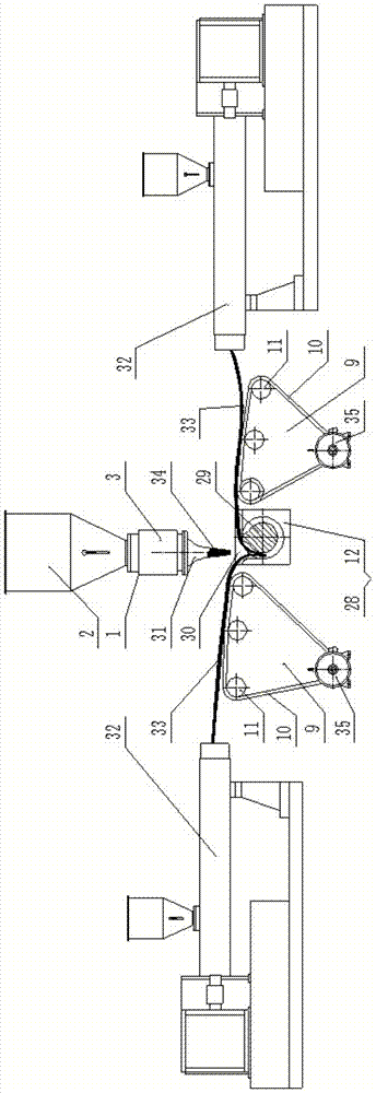
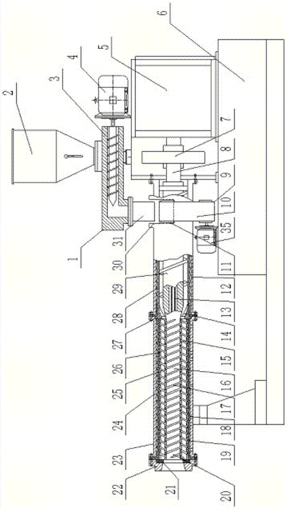
[0030] Such as figure 1 and figure 2 As shown, a rubber continuous mixing device of the present invention is mainly composed of compounding agent metering supply device 1, film metering and conveying device 9, barrel 22, main screw 20, planetary screw 15, rear brake ring 27, front brake ring 21. Die 22, transmission device 7, drive device 5, frame 6, etc., main screw 20 is composed of screw planetary section 16, screw feeding section 29 and screw transmission section 8 in turn, and the center of main screw 20 is from the transmission section 8. Blind holes are opened, and the cooling pipeline 13 is installed inside; the barrel 23 is composed of the inner barrel 19 of the planetary section, the outer barrel 24 of the planetary section, the inner barrel 28 of the feeding section, and the outer barrel 12 of the feeding section, and the inner barrel of the planetary section 19 is located inside the outer barrel 24 of the planetary section and is fixedly connected with it. The in...

Embodiment 2

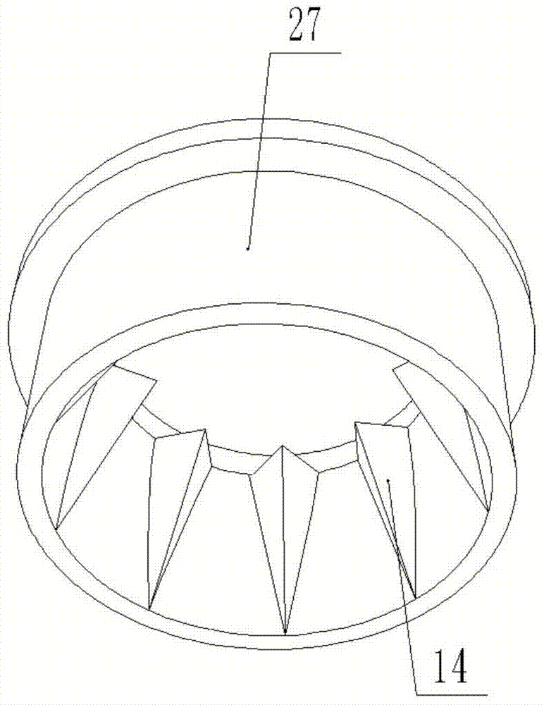
[0035] Such as Figure 7 As shown, the structure, working principle and effect of this embodiment and embodiment 1 are basically the same, the difference is: its blade 14 is not arranged on the rear brake ring 27, but is arranged on the feeding material contacting with the rear brake ring 27 rear end The position of the inner wall of the cylinder 28 in the section.

[0036] Because the material is not conveyed in a straight line forward along the axial direction of the machine barrel 23 in the process of advancing, but there is a certain helical angle. The blade 14 for cutting material will be subject to the lateral force of the material, and the blade 14 is arranged on the barrel 28 in the feeding section instead of on the rear brake ring 27, which will reduce the external force on the rear brake ring 27 and slow down the rear brake ring 27. Damage to the moving ring 27.

Embodiment 3

[0038] Such as Figure 8 As shown, the structure, working principle and effect of this embodiment are basically the same as those of Embodiment 1, the difference is that the front brake ring 21 has a hole, the planetary screw 15 and the front brake ring 21 are axially fixed and can rotate, and the planetary section The machine barrel 19 and the outer machine barrel 24 of the planetary section are axially fixed and rotatable. The number of blades of the rear brake ring 27 is consistent with the number of the planetary screw 15, and the circumferential position of each blade 14 is consistent with the circumferential position of the planetary screw 15. The number of the planetary screw 15 and the blades 14 should be large enough to ensure that the cross-sectional area of ​​the planetary screw gap is not greater than the cross-sectional area of ​​the planetary screw 15 .

[0039] The working principle of this structure is that the main screw 20 rotates and engages to make the plan...


PUM


Abstract

The invention belongs to the field of polymer molding processing, in particular to a rubber continuous mixing device, which mainly consists of a compounding agent metering supply device, a film metering and conveying device, a machine barrel, a main screw, a planetary screw, a brake ring, a die, and a transmission device The film metering and conveying device is located on both sides of the barrel, and the film is metered and delivered to the feeding port, and the compounding agent metering and supplying device is metered and delivered to the feeding port. In the barrel, it advances with the rotation of the screw, and is cut horizontally by the blade, so that the proportion of the material entering the gap of the planetary screw is basically the same, avoiding the poor dispersion caused by the light weight of the silica when the granular rubber is mixed with the silica. The uniform phenomenon enhances the mixing effect.

Description

technical field [0001] The invention belongs to the field of polymer molding processing, in particular to a rubber continuous mixing device. Background technique [0002] Silica has super strong adhesion, tear resistance, heat resistance and aging resistance. It can replace part of carbon black in rubber products to obtain high-quality rubber products. Tires made of silica-filled rubber have low Rolling resistance, good road surface skid resistance and winter driving characteristics, etc., so its application in automobile tires is increasing. [0003] Compound mixing is the first and most important step in the production of rubber products. Traditional silica-filled compounds are generally mixed in at least three steps using an internal mixer, which is a process with high energy consumption and high cost. The internal mixer acts as a chemical reactor, and the reaction is carried out within the temperature range of 140°C to 150°C, and the mixing time is 3min to 4min. In or...

Claims


Application Information

Patent Timeline
Patent Type & Authority Patents(China)
IPC IPC(8): B29B7/14B29B7/22
Inventor 杨卫民刘海超谭晶焦志伟阎华谢鹏程丁玉梅
Owner BEIJING UNIV OF CHEM TECH
Why Eureka
Try Eureka