Lubricating oil conveying device of internal combustion engine with four cylinders surrounding shaft

A conveying device and lubricating oil technology, applied in the direction of engine lubrication, pressure lubricant, mechanical equipment, etc., can solve the problems of increased manufacturing cost of internal combustion engines, fast wear and tear of internal combustion engines, increased volume of internal combustion engines, etc., to achieve improved service life, The effect of saving space and increasing strength

Active Publication Date: 2015-11-11
齐艳华
View PDF7 Cites 33 Cited by
  • Summary
  • Abstract
  • Description
  • Claims
  • Application Information

AI Technical Summary

Problems solved by technology

[0003] However, at present, the fundamental task of the lubricating oil delivery device for internal combustion engines is to continuously supply lubricating oil with clean, certain pressure and suitable temperature to the friction surfaces of moving parts so that the internal combustion engine can work normally. Therefore, the lubricating oil delivery device for internal combustion engines must have An oil pump with sufficient oil pressure, but there are some problems when using an oil pump in an internal combustion engine: 1. As a component, the oil pump needs to occupy a certain amount of space in the internal combustion engine, resulting in an increase in the volume of the internal combustion engine. As an independent operating part, the oil pump It must consume a certain amount of energy; 2. Due to the complex structure of the crankshaft, the lubricating oil needs to be under a strong pressure to ensure that the crankshaft is well lubricated and protected. The tile or locking phenomenon occurs, so that the internal combustion engine wears quickly and the life is short; 3. The cost of the oil pump is relatively high, and as a necessary part of the internal combustion engine, the manufacturing cost of the internal combustion engine increases

Method used


Image

  • Lubricating oil conveying device of internal combustion engine with four cylinders surrounding shaft
  • Lubricating oil conveying device of internal combustion engine with four cylinders surrounding shaft
  • Lubricating oil conveying device of internal combustion engine with four cylinders surrounding shaft

Examples


Embodiment Construction

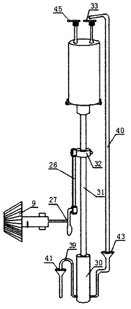
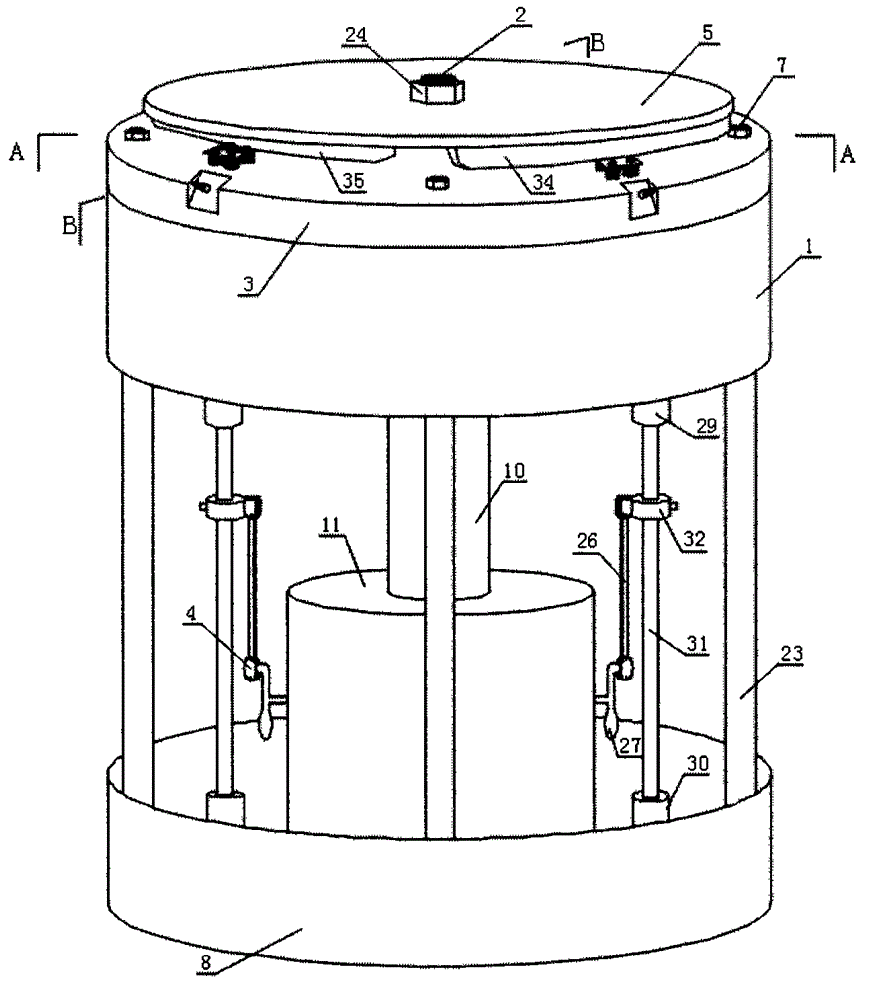
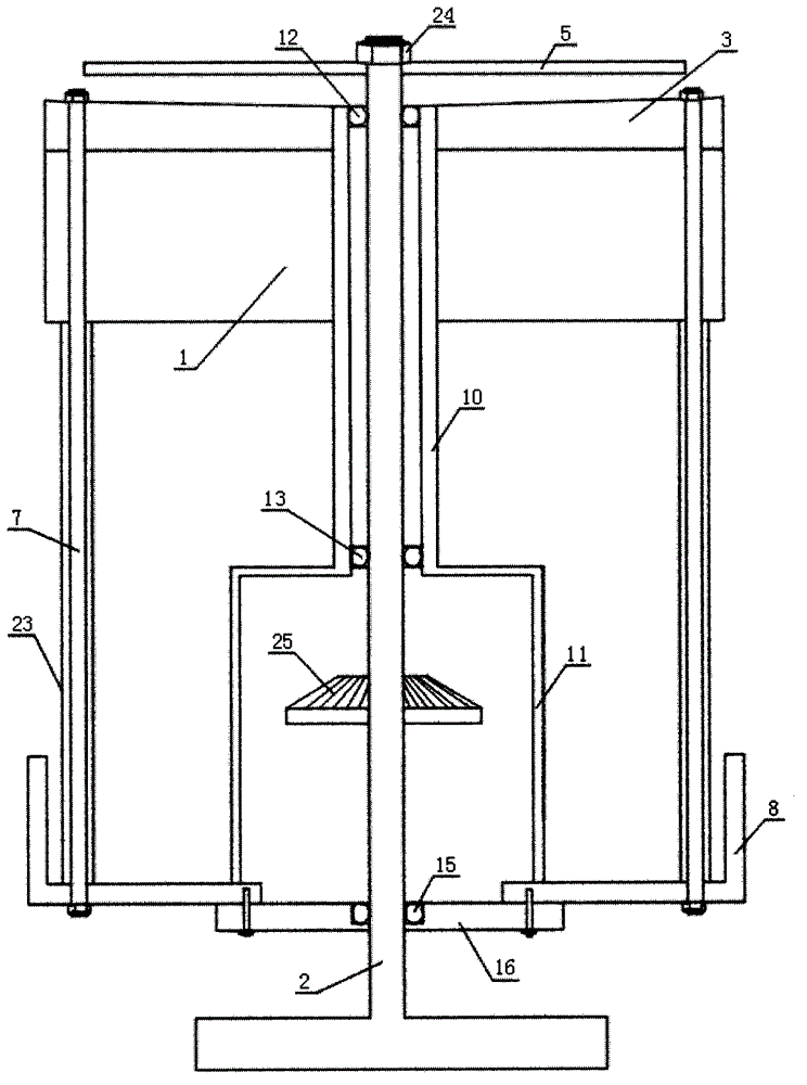
[0021] Such as figure 1 and Figure 4 As shown, the internal combustion engine of this embodiment includes a cylinder block 1, an output power shaft 2, a cylinder head 3, a crankshaft connecting rod device 4, a cam disc 5, an anti-eccentric wear device and a lubricating oil delivery device, and the cylinder block 1 is provided with cylinder holes 18 and piston 28, crankshaft connecting rod device 4 includes crankshaft 27, connecting rod 26 and crankshaft gear 9, anti-eccentric wear device includes upper bushing 29, lower bushing 30 and piston guide rod 31, lubricating device 6 is provided with lubricating oil tank 8, The lubricating oil delivery device is provided with an oil suction anti-backflow valve 37, an oil injection anti-backflow valve 38, an oil suction pipe 39 and an oil injection pipe 40. The lower end of the lower bushing 30 is fixed on the bottom plate of the lubricating oil tank 8. It communicates with the bottom of the lower bushing 30, the open end of the oil ...


PUM


Abstract

The invention discloses a lubricating oil conveying device of an internal combustion engine with four cylinders surrounding a shaft, and relates to the field of internal combustion engines. The lubricating oil conveying device solves the problems that an existing internal combustion engine is large in machining difficulty, prone to abrasion, high in energy consumption and the like. The lubricating oil conveying device is provided with oil suction backflow preventing valves, oil spray backflow preventing valves, oil suction pipes and oil spray pipes; the lower ends of lower shaft sleeves are fixed at the bottom of a lubricating oil tank, the oil suction pipes and the oil spray pipes are both communicated with the bottom ends of the lower shaft sleeves, the opening ends of the oil suction pipes are placed on a base plate of the lubricating oil tank, and openings of the oil spray pipes are placed on the outer side of an air suction valve cam of a cam plate; the oil spray backflow preventing valves are fixedly connected to the oil suction pipes, and the oil spray backflow preventing valves are fixedly connected to the oil spray pipes. The lubricating oil conveying device has the advantages of being simple in structure, convenient to use, small in energy consumption and capable of lowering the cost and saving the space.

Description

technical field [0001] The invention relates to the field of internal combustion engines, in particular to a lubricating oil delivery device for an internal combustion engine with four cylinders around one shaft. Background technique [0002] At present, when the internal combustion engine is working, the internal components of the internal combustion engine perform relative motion at a very high speed. The friction between the internal combustion engine components such as the crankshaft journal and the connecting rod journal, the camshaft journal and the bearing, the piston and the cylinder wall, etc. Not only does it increase the power consumption of the internal combustion engine, but the heat generated by friction may also melt the surface of some working parts and rapidly wear the working surfaces of some parts of the internal combustion engine, thus causing the internal combustion engine to fail to operate normally. Therefore, in order to ensure that the internal combu...

Claims


Application Information

Patent Timeline
Patent Type & Authority Applications(China)
IPC IPC(8): F01M1/04
Inventor 武克学武成阁
Owner 齐艳华
Why Eureka
Try Eureka