Anti-crystallization device for carbamide nozzle of selective catalytic reduction (SCR) system

A technology of SCR system and urea nozzle, which is used in muffler devices, exhaust devices, engine components, etc., can solve the problems of poor interchangeability and versatility, complicated manufacturing, and high manufacturing costs, and reduce the risk of crystal blockage. The effect of simplifying the structure of the mounting support, low production and maintenance costs

Active Publication Date: 2015-11-11
山东艾泰克环保科技股份有限公司
View PDF7 Cites 4 Cited by
  • Summary
  • Abstract
  • Description
  • Claims
  • Application Information

AI Technical Summary

Problems solved by technology

The disadvantages of this solution are: special branch pipes need to be added to the exhaust pipe, which is complicated to manufacture, and the interchangeability and versatility are not good; If there is leakage, it may cause the water pressure of the engine cooling system to be low and cause the engine to fail to work normally; in addition, the nozzle of this solution will still be in direct contact with the high-temperature exhaust gas

Method used


Image

  • Anti-crystallization device for carbamide nozzle of selective catalytic reduction (SCR) system
  • Anti-crystallization device for carbamide nozzle of selective catalytic reduction (SCR) system
  • Anti-crystallization device for carbamide nozzle of selective catalytic reduction (SCR) system

Examples


Embodiment 1

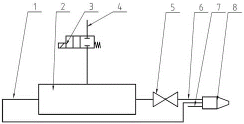
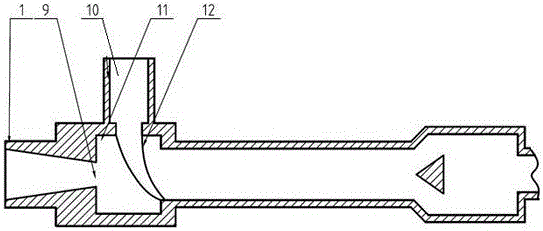
[0016] Embodiment 1, with reference to figure 1 , figure 2 , image 3 , comprising a solenoid valve 3, a vortex tube assembly 2, and a nozzle assembly 8, the air inlet 4 of the vortex tube assembly 2 is provided with a solenoid valve, and one end of the vortex tube assembly 2 passes through the cold air pipeline 1 and the nozzle assembly 8, the other end is connected to the nozzle assembly 8 through the hot gas pipeline 6, the nozzle assembly 8 is also provided with a urea inlet 7, and the end of the nozzle assembly 8 is provided with a urea spout 15, a hot gas spout 13, and a cold air spout 14, The urea nozzle 15 is embedded in the cold air nozzle 14 , and the cold air nozzle 14 is embedded in the hot gas nozzle 13 .

Embodiment 2

[0017] Embodiment 2, the anti-crystallization device of the urea nozzle of the SCR system described in Embodiment 1: the vortex tube assembly includes a vortex chamber 11 and a vortex tube inlet 10, and the vortex chamber 11 is provided with a semi-open cavity, The cavity is an air inlet nozzle 12, and the air inlet nozzle 12 is connected to the air inlet 10 of the vortex tube;

Embodiment 3

[0018] Embodiment 3, the anti-crystallization device of the urea nozzle of the SCR system described in Embodiment 1: the hot gas pipeline 6 is provided with an electric control valve 5 for adjusting the output of hot gas;


PUM


Abstract

Disclosed is an anti-crystallization device for a carbamide nozzle of a selective catalytic reduction (SCR) system. The anti-crystallization device comprises a solenoid valve, a vortex tube assembly and a spray head assembly. A gas inlet of the vortex tube assembly is provided with the solenoid valve. One end of the vortex tube assembly is connected with the spray head assembly through a cool gas pipeline, and the other end of the vortex tube assembly is connected with the spray head assembly through a hot gas pipeline. The spray head assembly is further provided with a carbamide inlet. The tail end of the spray head assembly is provided with a carbamide nozzle orifice, a hot gas nozzle orifice and a cool gas nozzle orifice. The carbamide nozzle orifice is nested in the cool gas nozzle orifice. The cool gas nozzle orifice is nested in the hot gas nozzle orifice. Compressed gas can be transformed into cool gas flow and hot gas flow. The cool gas flow can be used for cooling components in the spray head assembly. The hot gas flow can be used for heating carbamide. The cool gas flow and the hot gas flow finally produce gas curtains through the nozzle orifices and the gas curtains isolate carbamide mist and high-temperature tail gas at the nozzle, and carbamide crystallization produced at the nozzle is avoided to the greatest extent. At the same time, cooling and heating effects are achieved in different positions simply and reliably; the production and maintenance cost of the system is low.

Description

technical field [0001] The invention relates to the technical field of engine exhaust gas treatment, in particular to an anti-crystallization device for a urea nozzle of an SCR system. Background technique [0002] SCR (Selective Catalytic Reduction, Selective Catalytic Reduction), refers to the use of catalysts to catalytically reduce the nitrogen oxides in diesel engine exhaust into nitrogen and water. As far as the engine exhaust aftertreatment system is concerned, the urea needs to be atomized and sprayed into the exhaust pipe to participate in the catalytic reduction reaction. Evaporation can easily cause urea to crystallize and adhere to the small holes of the nozzle, thereby clogging the nozzle, which is especially obvious in the stage of small-dose injection. [0003] At present, there are roughly two types of devices on the market to solve nozzle clogging. One is to wrap ceramic insulation material around the nozzle to reduce the heat absorbed by the nozzle body fr...

Claims


Application Information

Patent Timeline
Patent Type & Authority Applications(China)
IPC IPC(8): F01N3/28
Inventor 赵伟檀荣科王用林孙克亮
Owner 山东艾泰克环保科技股份有限公司
Why Eureka
Try Eureka