An outer edge fixed laser processing piezoelectric driven multi-ring gyroscope and its preparation method

A laser processing, piezoelectric drive technology, applied in gyroscope/steering sensing equipment, gyro effect for speed measurement, speed/acceleration/shock measurement, etc. Complex process and other problems, to achieve the effect of simple processing steps, reduced impact, and stable gyro structure

Active Publication Date: 2018-02-09
SHANGHAI JIAO TONG UNIV
View PDF5 Cites 0 Cited by
  • Summary
  • Abstract
  • Description
  • Claims
  • Application Information

AI Technical Summary

Problems solved by technology

[0005] This technology has the following disadvantages: the hemispherical resonant gyroscope is difficult to process because it involves spherical processing, and the process error is difficult to control; the cavity of the hemispherical resonator is obtained by etching, and the sphericity is not high enough, and the sphericity of the hemispherical resonator largely depends on the hemisphere The cavity of the resonator has a great influence on the performance of the gyro; the contact area between the hemispherical resonator and the support body of the gyro is small, and there is a possibility of fracture under high-frequency vibration, and the reliability is not high; the processing technology of the gyro is relatively complicated. High processing cost, not suitable for mass production

Method used


Image

  • An outer edge fixed laser processing piezoelectric driven multi-ring gyroscope and its preparation method
  • An outer edge fixed laser processing piezoelectric driven multi-ring gyroscope and its preparation method
  • An outer edge fixed laser processing piezoelectric driven multi-ring gyroscope and its preparation method

Examples


Embodiment

[0053] The present invention will be described in detail below in conjunction with specific embodiments. The following examples will help those skilled in the art to further understand the present invention, but do not limit the present invention in any form. It should be noted that those skilled in the art can make several modifications and improvements without departing from the concept of the present invention. These all belong to the protection scope of the present invention.

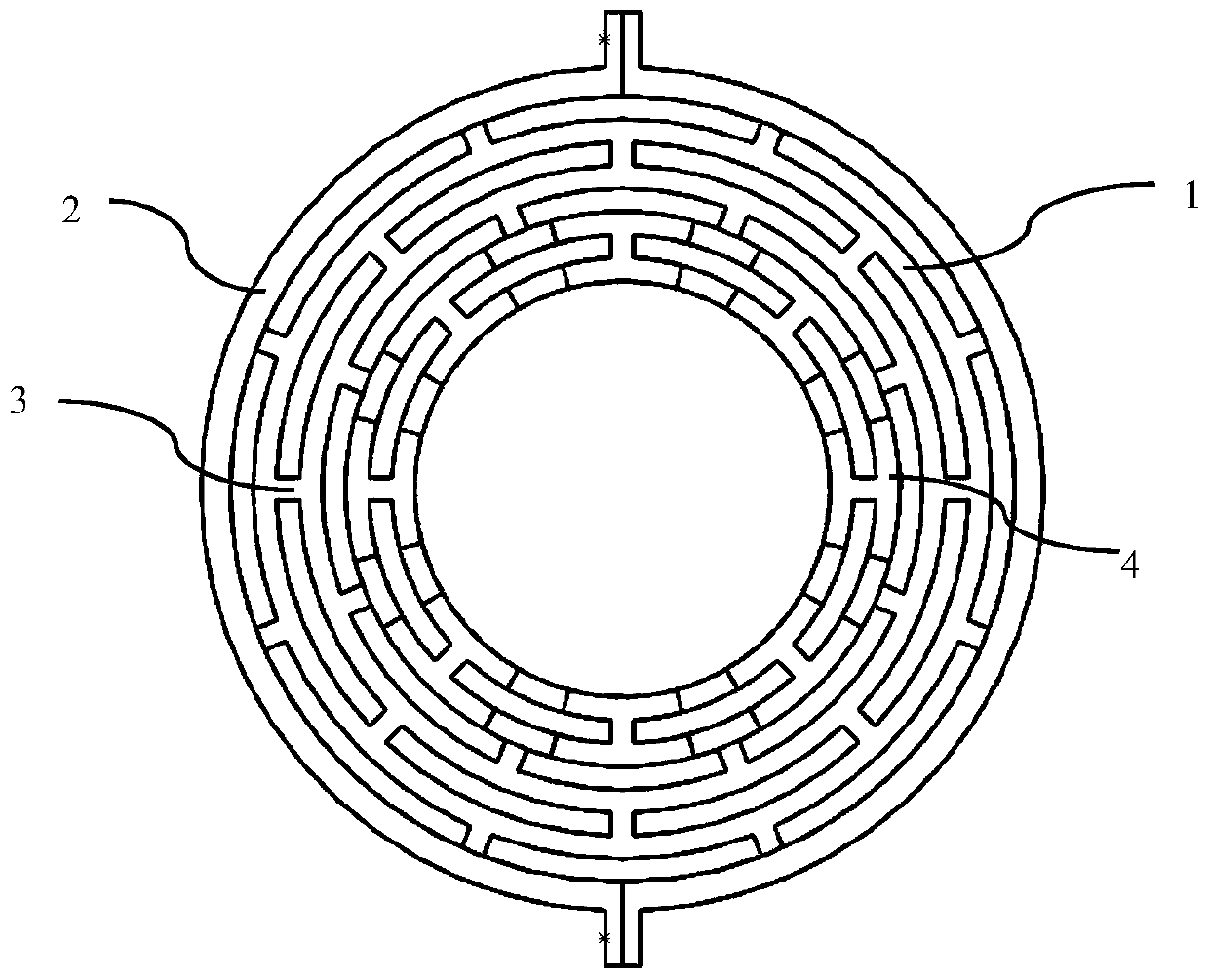
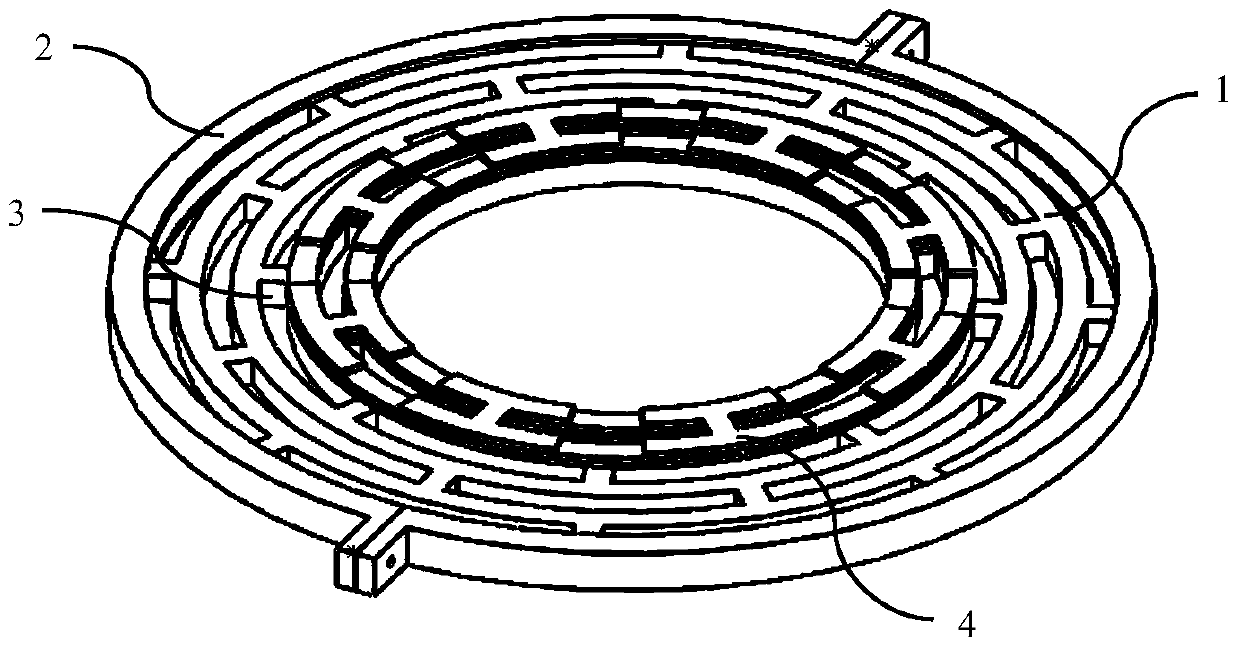
[0054] Such as Figure 1A , 1B As shown, the present embodiment provides an outer edge fixed piezoelectric driven multi-ring gyroscope, including:

[0055] a multi-ring resonator1 containing five to eight rings;

[0056] A fixed chute 2 supporting the multi-ring resonator;

[0057] Four to seven groups of spokes 3 located between two adjacent rings of the multi-ring resonator are used to connect rings and rings of the multi-ring resonator, and the positions of adjacent two groups of spokes have ...


PUM


Abstract

The invention provides an outer edge fixed type multi-ring gyroscope subjected to laser processing and piezoelectric actuation, and a preparation method thereof. The gyroscope comprises a multi-ring resonator containing 5-8 rings, a fixed chute for supporting the multi-ring resonator, multiple groups of spokes positioned between the two adjacent rings of the multi-ring resonator, and an electrode positioned on the upper surface of the multi-ring resonator, wherein the multiple groups of spokes are used for connecting the rings of the multi-ring resonator, and an angle difference is formed at the positions of the two adjacent groups of spokes; the outermost circle of the ring of the multi-ring resonator is fixed, and can vibrate freely only in the radial direction. The electrode is a piezoelectric material, and the gyroscope adopts the piezoelectric actuation mode when working. The gyroscope is fixed by the external edge of the multi-ring resonator, is arranged at the center of the rings in the electrode, has the advantages of small volume, stable structure, sensitive responding, and the like, and has good symmetry, thus achieving relatively high performance.

Description

technical field [0001] The invention relates to a solid wave mode matching gyroscope in the field of micro-electromechanical technology, in particular to an outer edge fixed piezoelectric-driven multi-ring gyroscope and a preparation method thereof. Background technique [0002] Gyroscope is an inertial device that can be sensitive to the angle or angular velocity of the carrier, and it plays a very important role in the fields of attitude control, navigation and positioning. With the development of national defense technology and aviation and aerospace industries, the requirements of inertial navigation systems for gyroscopes are also developing in the direction of low cost, small size, high precision, multi-axis detection, high reliability, and adaptability to various harsh environments. The micro gyroscope based on MEMS technology is processed by micro-nano batch manufacturing technology, its cost, size, and power consumption are very low, and its environmental adaptabili...

Claims


Application Information

Patent Timeline
Patent Type & Authority Patents(China)
IPC IPC(8): G01C19/5684G01C25/00
CPCG01C19/5684G01C25/00
Inventor 张卫平邢亚亮唐健孙殿竣汪濙海刘亚东陈文元
Owner SHANGHAI JIAO TONG UNIV
Why Eureka
Try Eureka