
Polarization-independent type photo-isolator and magneto-optical crystal device manufacturing method

A technology of magneto-optic crystals and optical isolators, which is applied in the fields of instruments, optics, nonlinear optics, etc., can solve the problems of not being able to use optical glue and increasing the insertion loss of optical isolators, and achieve the effect of reducing interface reflection and insertion loss

Inactive Publication Date: 2015-11-11
TECHNICAL INST OF PHYSICS & CHEMISTRY - CHINESE ACAD OF SCI
View PDF6 Cites 2 Cited by
  • Summary
  • Abstract
  • Description
  • Claims
  • Application Information

AI Technical Summary

Problems solved by technology

Since the crystal used to make the angle wedge is different from the crystal of the magneto-optic crystal device, the two cannot be optically glued, and there will be interface reflection when the parallel beam passes between the two angle wedges and the magneto-optic crystal device, thereby increasing the insertion of the optical isolator loss

Method used


Image

  • Polarization-independent type photo-isolator and magneto-optical crystal device manufacturing method
  • Polarization-independent type photo-isolator and magneto-optical crystal device manufacturing method
  • Polarization-independent type photo-isolator and magneto-optical crystal device manufacturing method

Examples


Embodiment 1

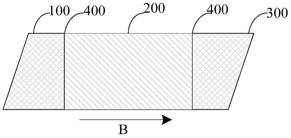
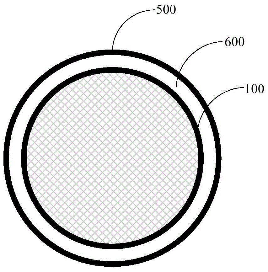
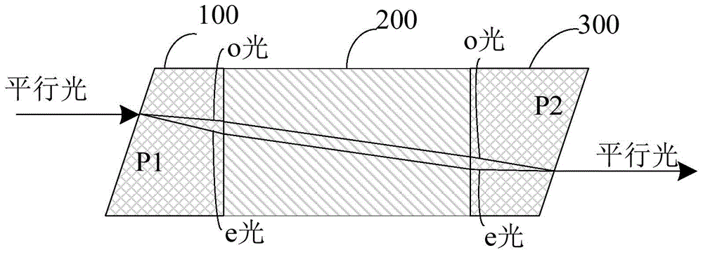
[0028] Such as figure 1 versus figure 2 As shown, the embodiment of the present invention provides a polarization-independent isolator, including: a first fiber collimator ( figure 1 Not shown in), the second optical fiber collimator ( figure 1 Not shown in), the magnetic ring, the first crystal wedge plate 100, the second crystal wedge plate 300 and the magneto-optical crystal device 200, the first crystal wedge plate 100 and the second crystal wedge plate 300 are made by photo-glue They are respectively fixed at both ends of the magneto-optical crystal device 200; the magnetic ring 500 surrounds the magneto-optical crystal device 200 to provide a stable magnetic field for the magneto-optical crystal device; the first fiber collimator is arranged on the first crystal wedge plate 100 One side; the second fiber collimator is arranged on the side of the second crystal wedge plate 300; wherein, the first fiber collimator and the second fiber collimator are arranged on the optical p...

Embodiment 2

[0033] In order to realize that the first crystal wedge plate 100 and the second crystal wedge plate 300 are respectively fixed to the two ends of the magneto-optical crystal device 200 by photoresist, the crystal axis clamps of the first crystal wedge plate and the second crystal wedge plate The angle is set to 45 degrees. Optionally, in the embodiment of the present invention, crystals of the same crystal space group are used to form the first crystal wedge plate, the second crystal wedge plate and the magneto-optical crystal device. For example, the first crystal wedge plate and the second crystal wedge plate use yttrium barium oxide (YVO 4 ) Crystal, magneto-optical crystal device adopts terbium vanadate (TbVO 4 ) Crystal or doped terbium vanadate (TbVO 4 ) Crystal made.

[0034] The embodiment of the present invention is made by using the crystals of the same crystal space group to realize the first crystal wedge, the second crystal wedge and the magneto-optical crystal devi...

Embodiment 3

[0040] In order to embody the superiority of a polarization-independent isolator provided by the present invention, an embodiment of the present invention also provides a method for manufacturing a magneto-optical crystal device, such as Figure 5 Shown, including:

[0041] Orient the magneto-optical crystal and determine the optical axis of the magneto-optical crystal;

[0042] Cut the magneto-optical crystal along the optical axis to form a long magneto-optical crystal;

[0043] Rounding the strip magneto-optical crystal to form a cylindrical magneto-optical crystal;

[0044] Both ends of the cylindrical magneto-optical crystal are optically polished and coated to form a magneto-optical crystal device.

[0045] Optionally, the magneto-optical crystal device is made of calcium terbium vanadate crystal.

[0046] Optionally, the magneto-optical crystal device has a diameter of 3-15 mm and a length of 8-50 mm.

[0047] In summary, the embodiments of the present invention provide a method f...


PUM

PropertyMeasurementUnit
wavelengthaaaaaaaaaa
diameteraaaaaaaaaa
lengthaaaaaaaaaa

Abstract

The invention relates to a polarization-independent type photo-isolator. The polarization-independent type photo-isolator comprises a first crystal wedge angle piece and a second crystal wedge angle piece. The first crystal wedge angle piece and the second crystal wedge angle piece are fixed to the two ends of a magneto-optical crystal device respectively in an optical cement mode. During forward transmission, the first crystal wedge angle piece divides parallel light from a first optical collimator into light o and light e. The magneto-optical crystal device rotates the polarization faces of the light o and the light e in the identical direction by 45 degrees, so that the light o and the light e are transmitted to the second crystal wedge angle piece, and the second crystal wedge angle piece refracts the light o and the light e to form two beams of parallel light; during reverse transmission, the second crystal wedge angle piece divides parallel light from the second optical collimator into light o and light e, and at the moment, a first included angle is formed between the light o and the light e. The magneto-optical crystal device rotates the polarization face of the light o and the light e in the identical direction and then transmits the light to the first crystal wedge angle piece, the first crystal wedge angle piece refracts the light o and the light e to form light e and light o, and at the moment, a second included angle is formed between the light e and the light o, wherein the second included angle is larger than the first included angle. The insertion loss of the polarization-independent type photo-isolator can be lowered.

Description

Technical field [0001] The invention relates to the field of optoelectronic technology, in particular to a method for manufacturing a polarization-independent isolator and a magneto-optical crystal device. Background technique [0002] An optical isolator is an optical passive device that allows light to pass through in one direction and blocks light in the opposite direction. In some optical devices such as semiconductor lasers, optical amplifiers, and fiber lasers, they are very sensitive to reflected light from connectors, fusion splices, filters, etc., so optical isolators are required to prevent reverse light. Optical isolators can be divided into polarization-independent and polarization-dependent types according to their polarization characteristics. Both types of isolators use magneto-optical crystal devices with magneto-optical rotation effects. [0003] At present, polarization-independent optical isolators are widely used and usually include four main components: a magn...

Claims


Application Information

Patent Timeline
Patent Type & Authority Applications(China)
IPC IPC(8): G02F1/095
CPCG02F1/0955
Inventor 涂衡胡章贵赵营岳银超
Owner TECHNICAL INST OF PHYSICS & CHEMISTRY - CHINESE ACAD OF SCI
Learn More