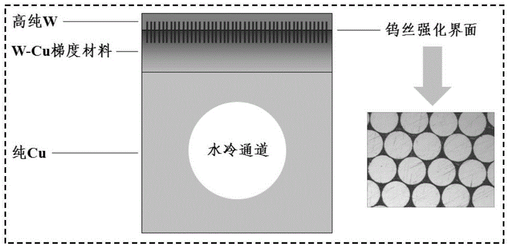
Divertor module and manufacturing method
A divertor and gradient alloy technology, applied in nuclear reactors, nuclear power generation, climate sustainability, etc., can solve problems such as interface failure and large thermal stress, and achieve the effect of improving interface bonding strength and relieving thermal stress
- Summary
- Abstract
- Description
- Claims
- Application Information
AI Technical Summary
Problems solved by technology
Method used
Image
Examples
Embodiment 1
[0037] The mixed powder of W and Cu is loaded into a graphite crucible and pressed into a billet, and a tungsten wire array is preset in the billet. Then Al powder and CuO powder are uniformly mixed according to the molar ratio of Al:CuO=2:3 and pressed into a billet, which is placed on the mixed powder billet of W and Cu. The graphite crucible is placed in the centrifugal force field (centrifugal force is 1000r / min), and the mixed powder compact of Al and CuO is ignited by electric heating, and the mixed powder compact of Al and CuO undergoes a violent combustion reaction, and the resulting high-temperature Cu melts The body rapidly infiltrates into the mixed powder blank of W and Cu under the action of centrifugal force. After the reaction is completed, the obtained product is divided into three layers, the upper layer is Al 2 o 3 , the middle layer is pure Cu, and the lower layer is a W / Cu gradient alloy containing tungsten wire arrays. Al 2 o 3 Remove, then smooth the...
Embodiment 2
[0040] The mixed powder of W and Cu is loaded into a graphite crucible and pressed into a billet, and a tungsten wire array is preset in the billet. Then Al powder and CuO powder are uniformly mixed according to the molar ratio of Al:CuO=2:3 and pressed into a billet, which is placed on the mixed powder billet of W and Cu. Put the graphite crucible in the centrifugal force field (centrifugal force is 5000r / min), and ignite the mixed powder blank of Al and CuO by means of electric heating, the mixed powder blank of Al and CuO undergoes a violent combustion reaction, and the high-temperature Cu melt produced Under the action of centrifugal force, it quickly penetrates into the mixed powder blank of W and Cu. After the reaction is completed, the obtained product is divided into three layers, the upper layer is Al 2 o 3 , the middle layer is pure Cu, and the lower layer is a W / Cu gradient alloy containing tungsten wire arrays. Al 2 o 3 Remove, then smooth the upper and lower ...
Embodiment 3
[0043] The mixed powder of W and Cu is loaded into a graphite crucible and pressed into a billet, and a tungsten wire array is preset in the billet. Then Al powder and CuO powder are uniformly mixed according to the molar ratio of Al:CuO=2:3 and pressed into a billet, which is placed on the mixed powder billet of W and Cu. Put the graphite crucible in the centrifugal force field (centrifugal force is 10000r / min), ignite the mixed powder blank of Al and CuO by means of electric heating, the mixed powder blank of Al and CuO undergoes violent combustion reaction, and the high temperature Cu melt produced Under the action of centrifugal force, it quickly penetrates into the mixed powder blank of W and Cu. After the reaction is completed, the obtained product is divided into three layers, the upper layer is Al 2 o 3, the middle layer is pure Cu, and the lower layer is a W / Cu gradient alloy containing tungsten wire arrays. Al 2 o 3 Remove, then smooth the upper and lower surfac...
PUM
| Property | Measurement | Unit |
|---|---|---|
| Interfacial bonding strength | aaaaa | aaaaa |
| Thickness | aaaaa | aaaaa |
| Thickness | aaaaa | aaaaa |
Abstract
Description
Claims
Application Information
 - R&D
- Intellectual Property
- Life Sciences
- Materials
- Tech Scout
- Unparalleled Data Quality
- Higher Quality Content
- 60% Fewer Hallucinations
Browse by: Latest US Patents, China's latest patents, Technical Efficacy Thesaurus, Application Domain, Technology Topic, Popular Technical Reports.
© 2025 PatSnap. All rights reserved.Legal|Privacy policy|Modern Slavery Act Transparency Statement|Sitemap|About US| Contact US: help@patsnap.com

