S-band microwave quadrature power divider

A microwave power divider and power divider technology are applied to waveguide-type devices, circuits, connecting devices, etc., to achieve the effects of excellent electrical performance, light weight, and simple circuit structure.

Inactive Publication Date: 2015-11-11
NANJING UNIV OF SCI & TECH
View PDF8 Cites 2 Cited by
  • Summary
  • Abstract
  • Description
  • Claims
  • Application Information

AI Technical Summary

Problems solved by technology

But there is no S-band microwave quadrature power splitter in the prior art

Method used


Image

  • S-band microwave quadrature power divider
  • S-band microwave quadrature power divider
  • S-band microwave quadrature power divider

Examples


Embodiment Construction

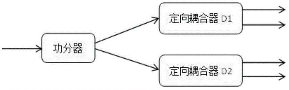
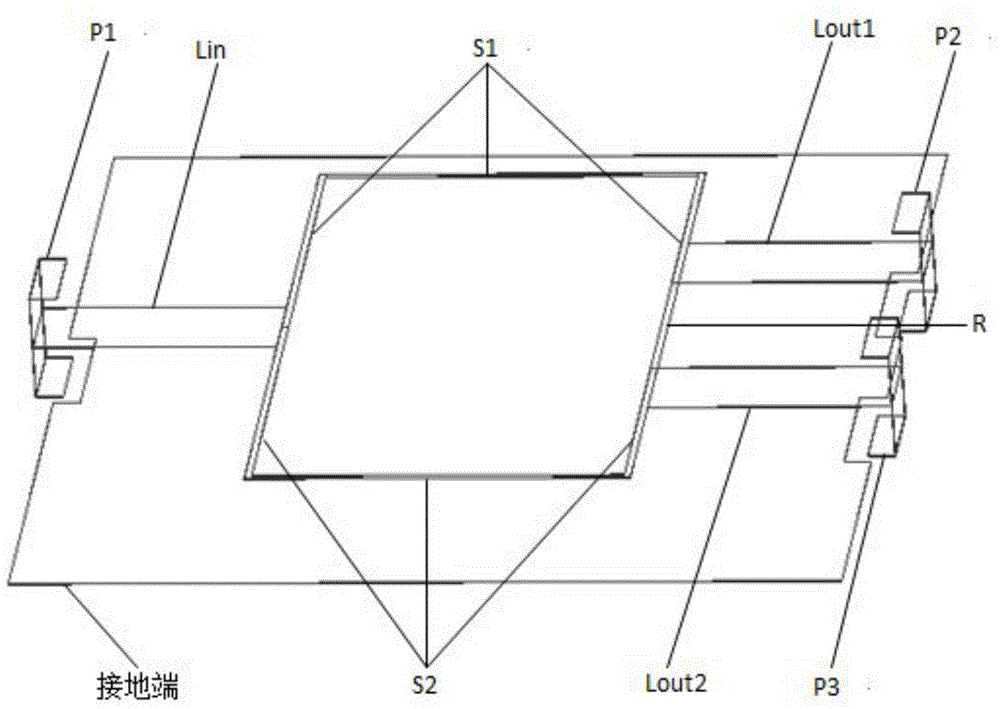
[0016]In conjunction with Fig. 1(a), Fig. 1(b), Fig. 1(c), Fig. 1(d), a kind of S-band microwave orthogonal power splitter of the present invention comprises a microwave power splitter and two directional couplers , the microwave power divider of the orthogonal power divider includes a surface-mounted 50-ohm impedance first input port P1, an input inductance Lin, a first λ / 4 transmission line S1, a second λ / 4 transmission line S2, and a 100-ohm resistance R , the first output inductance Lout1, the second output inductance Lout2, the surface mount 50 ohm impedance first output port P2, the surface mount 50 ohm impedance second output port P3 and the ground terminal. Among them, the left end of the input inductor Lin is connected to the surface-mounted 50-ohm impedance first input port P1, the right end is connected to the first λ / 4 transmission line S1 and the second λ / 4 transmission line S2, and the other end of the first λ / 4 transmission line S1 One end of the 100 ohm resisto...


PUM


Abstract

The invention relates to an S-band microwave quadrature power divider which comprises a microwave power divider and two directional couplers. The microwave power divider is composed of a specific compact structure and a three-dimensional integrated structure. The directional coupler comprises a surface-mounted input/output port and double-helix structured broadside coupled striplines. The above structures are realized by a multilayer low-temperature co-fired ceramics technology. According to the invention, four routes have the same output signal power. The power divider can generate quadrature phase, is easy to debug, is light in weight, has high reliability, good electrical property, good temperature stability and good electrical property batch consistency, is low-cost, can be used for mass production and is suitable for occasions and corresponding systems of corresponding microwave frequency band communication, satellite communications and the like which have strict requirements on volume, electrical property, temperature stability and reliability.

Description

technical field [0001] The invention relates to a power splitter, in particular to an S-band microwave orthogonal power splitter. Background technique [0002] Nowadays, whether it is military radar, electronic detection, electronic countermeasures, etc., or civilian mobile phone communication, TV, remote control, it is necessary to distribute and process electronic signals, which requires the use of an important microwave passive device—power divider ( Splitters). It is a microwave network that divides one signal into two or multiple signals. If it is used in reverse, it is a power combiner that synthesizes several signals into one signal. Now power splitters have been widely used in various in electronic equipment. [0003] With the rapid development of miniaturization of mobile communication, satellite communication and national defense electronic systems, high performance, low cost and miniaturization have become the development direction of the microwave / radio frequen...

Claims


Application Information

Patent Timeline
Patent Type & Authority Applications(China)
IPC IPC(8): H01P5/12
Inventor 周围杨茂雅戴永胜李博文陈烨刘毅乔冬春
Owner NANJING UNIV OF SCI & TECH
Why Eureka
Try Eureka