A Fractional Frequency Division Circuit for Spurious Suppression

A fractional frequency division and circuit technology, which is applied in the field of signal sources, can solve the problems of phase noise deterioration, low precision of fractional frequency, and high cost, so as to improve the level of phase noise and spurs, suppress spurs and phase noises, and reduce costs Effect

Active Publication Date: 2017-12-01
CHINA ELECTRONIS TECH INSTR CO LTD
View PDF4 Cites 0 Cited by
  • Summary
  • Abstract
  • Description
  • Claims
  • Application Information

AI Technical Summary

Problems solved by technology

The period of the party output sequence is very short, and the quantization noise power is distributed on a limited number of frequency points at the sampling frequency, resulting in the generation of the quantization noise spectral component (Idle Tone) of the modulator, which further deteriorates the spectral purity of the frequency synthesizer output signal
In summary, the fractional frequency division circuit in the prior art has the following disadvantages: 1. The ASIC chip frequency synthesizer has a long cycle, high cost, low precision of the fractional frequency, single function, and cannot perform frequency modulation and equalization functions. The dithering scheme has not been given yet
2. The frequency synthesizer of the board-level digital-analog hybrid circuit, due to internal clock jitter and circuit delay and the mismatch of the digital-analog hybrid circuit interface, has an unstable output frequency division ratio, resulting in output signal spurious and phase Noise deterioration
3. There is a limit cycle phenomenon in the Σ-Δ modulator of FPGA, which causes spurious signal deterioration

Method used


Image

  • A Fractional Frequency Division Circuit for Spurious Suppression
  • A Fractional Frequency Division Circuit for Spurious Suppression

Examples


Embodiment Construction

[0023] Below in conjunction with accompanying drawing and specific embodiment the present invention is described in further detail:

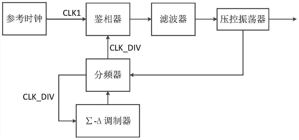
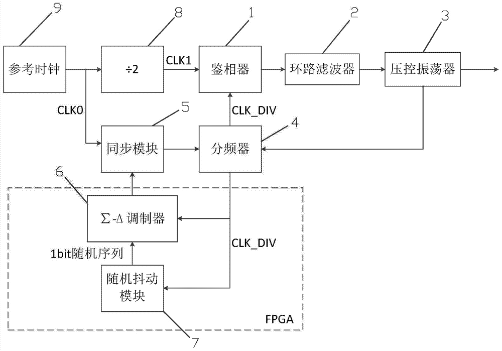
[0024] A fractional frequency division circuit for spurious suppression, including a phase detector 1, a loop filter 2, a voltage-controlled oscillator 3, a frequency divider 4, a synchronization module 5, a Σ-Δ modulator 6, and a random dithering module 7 and a divide-by-two frequency divider of 8.

[0025] Among them, the phase detector 1, the loop filter 2, the voltage-controlled oscillator 3, the frequency divider 4, the synchronization module 5 and the two-frequency divider 8 are all analog circuit devices; the Σ-Δ modulator 6 and the random dithering Module 7 is a digital circuit device, implemented in FPGA.

[0026] The divide-by-two frequency divider 8, the phase detector 1, the loop filter 2 and the voltage-controlled oscillator 3 are connected in sequence.

[0027] One output signal of the voltage-controlled oscillator 3 is directly ...


PUM


Abstract

The invention belongs to the field of signal sources, and specifically discloses a fractional frequency division circuit for stray suppression. The fractional frequency division circuit includes a phase detector, a loop filter, and a voltage-controlled oscillator connected in sequence; in addition, the fractional frequency division circuit also includes a frequency divider, a synchronization module, and a Σ-Δ modulator; wherein, the voltage-controlled oscillation The output signal of the detector, one way is directly output, and the other way is fed back to the frequency divider; the reference clock signal is divided into two ways, one way is divided by two and enters the phase detector as the phase detector reference clock signal, and the other way is used as the clock signal of the synchronization module , used to beat the frequency division ratio generated by the Σ-Δ modulator into the frequency divider; one way of the frequency-divided clock signal generated by the frequency divider enters the phase detector, and the other enters the Σ-Δ modulator and is used as a Σ-Δ modulation device clock signal. Compared with the fractional frequency division circuit in the prior art, the present invention adds a frequency divider and a synchronization module, and at the same time adds a random jitter module inside the FPGA to suppress the limit cycle phenomenon, further reducing spurs.

Description

technical field [0001] The invention belongs to the field of signal sources and relates to a fractional frequency division circuit for stray suppression. Background technique [0002] With the development of modern radar and radio communication technologies, various electronic devices have continuously put forward higher requirements for the frequency synthesizers used in their internal applications or system tests. Among them, the important point is to have extremely high frequency resolution and excellent phase noise. For example, a high-performance synthetic signal generator used for measurement and calibration usually requires the output frequency resolution of its frequency synthesizer to reach the order of Hz or even higher. In order to meet the system's requirements for high frequency resolution and low noise, fractional frequency synthesis technology has been widely used in recent years. However, due to the control of the frequency division ratio of the loop feedba...

Claims


Application Information

Patent Timeline
Patent Type & Authority Patents(China)
IPC IPC(8): H03L7/18H03L7/099
Inventor 周帅樊晓腾刘亮何攀峰范吉伟
Owner CHINA ELECTRONIS TECH INSTR CO LTD
Why Eureka
Try Eureka