Clamp special for detecting thermocouple and method for detecting thermocouple

A special fixture and thermocouple technology, applied in the direction of measuring heat, manufacturing tools, workpiece clamping devices, etc., can solve the problems that the alligator clip cannot meet the parasitic potential, is easily affected by the fluctuation of ambient temperature, and increases the error component of the verification result, etc. Achieve the effects of shortening the verification operation process, improving verification efficiency, and avoiding negative effects

Active Publication Date: 2015-11-18
泰安磐然测控科技有限公司
View PDF5 Cites 3 Cited by
  • Summary
  • Abstract
  • Description
  • Claims
  • Application Information

AI Technical Summary

Problems solved by technology

[0003] The current problems of the above test devices and methods: During the thermocouple verification process, the reference terminals of the tested thermocouple and the standard thermocouple need to be well connected with the copper wire connected to the electrical measuring equipment, and the temperature compensation of the reference terminal of the thermocouple is performed.
If a freezing point device is used as reference terminal compensation, it is usually necessary to connect multi-strand copper wires and galvanic wires by twisting. The connection method of twisting together has the following problems: 1. The wiring operation is cumbersome and the efficiency is very low.
If the couple to be detected is an armored thermocouple, it is necessary to use an additional compensation wire to lead the positive and negative poles on the flange at the rear end of the thermocouple into the freezing point bottle, which is very troublesome to operate.
2. Copper wires are easily oxidized and need to be sanded frequently to ensure good contact. As a result, the connecting wires are getting shorter and shorter
3. The thermocouple wire will break if it is often twisted
If the external temperature sensor reference terminal compensation method is used for verification, the alligator clip is usually used for connection. The connection method of the alligator clip will bring the following problems: 1. The conventional alligator clip usually cannot meet the requirements for the parasitic potential in the verification process, and the industry regulations stipulate The parasitic potential should be lower than 0.4μV, and ordinary alligator clips cannot meet the standard requirements
2. There is a deviation in the temperature compensation of the reference terminal. The main reason here is that during the working process of the thermocouple, the working terminal will transfer heat to the reference terminal, especially for a relatively short thermocouple, so the temperature of the reference terminal is actually higher than the ambient temperature. The external reference terminal sensor can only measure room temperature, so the method of using an external reference terminal is easy to operate, but the error is large
3. There are many galvanic couples in the verification process, and the temperature of their reference junctions is not the same, but usually only one external reference junction compensation is used, so using the same external reference junction compensation will also cause relatively large errors in measurement results
4. The galvanic wire of the thermocouple is usually relatively thin, which is easily affected by the fluctuation of the ambient temperature, thereby increasing the error component in the verification result

Method used


Image

  • Clamp special for detecting thermocouple and method for detecting thermocouple
  • Clamp special for detecting thermocouple and method for detecting thermocouple
  • Clamp special for detecting thermocouple and method for detecting thermocouple

Examples


Embodiment Construction

[0028] Reference will now be made in detail to the exemplary embodiments, examples of which are illustrated in the accompanying drawings. When the following description refers to the accompanying drawings, the same numerals in different drawings refer to the same or similar elements unless otherwise indicated. The implementations described in the following exemplary examples do not represent all implementations consistent with the present invention. Rather, they are merely examples of means consistent with aspects of the invention as recited in the appended claims.

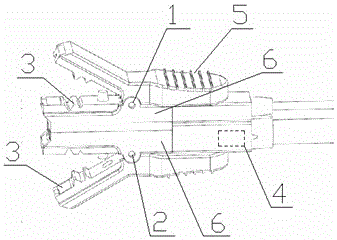
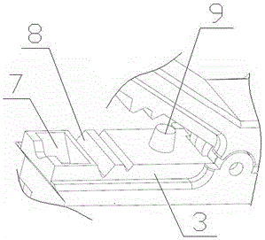
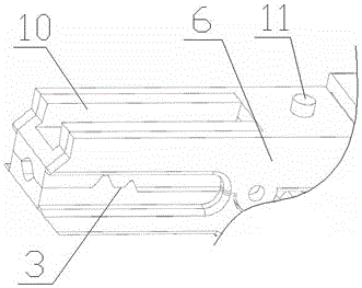
[0029] A special fixture for thermocouple verification, which includes a clamp body A1 and a clamp body B2 connected together, the clamp body A1 is used to connect the positive pole of the thermocouple, the clamp body B2 is used to connect the negative pole of the thermocouple, and the clamp bodies A and B are both set There is a spring clip structure. The front end of the spring clip structure is the clip 3. The...


PUM

PropertyMeasurementUnit
thicknessaaaaaaaaaa

Abstract

The invention discloses a clamp special for detecting a thermocouple. The clamp comprises a clamp body A and a clamp body B connected together. The clamp body A is used for being connected with the positive electrode of the thermocouple, the clamp body B is used for being connected with the negative electrode of the thermocouple, and the clamp body A and the clamp body B are both provided with spring clip structures. Clip mouths are arranged at the front ends of the spring clip structures, and metal materials good in heat conducting property are adopted by an inner core of the clamp body A, an inner core of the clamp body B and clamping openings of the clip mouths of the clamp bodies. The clamp body A and the clamp body B are connected in a contact mode and are insulated from each other. A temperature sensor is arranged in the tail end of the clamp body B and is connected with external electrical logging equipment through a data wire. Signal lines are welded to the metal tail ends of the inner cores inside the clamp body A and the clamp body B and connected to the external electrical logging equipment. Compared with an existing detecting device and method, the clamp is reasonable in structure design, convenient to operate and use, simple in measuring process and high in measuring precision.

Description

technical field [0001] The invention relates to a thermocouple detection device and a method thereof, in particular to a special fixture for thermocouple verification and a thermocouple verification method. Background technique [0002] Thermocouple is the most commonly used sensor in the temperature measurement industry. Its temperature measurement principle is based on the principle of thermoelectric effect, that is, two conductors with different components are welded or spliced ​​together. A thermoelectric potential is generated in the circuit, and the temperature is measured by measuring the magnitude of the thermoelectric potential. During the use of thermocouples, due to high-temperature volatilization of thermodes, changes in grain structure, oxidation and corrosion, etc., aging and deterioration often occur, which changes the thermoelectric characteristics and causes temperature measurement errors. In order to make its temperature measurement accurate, the working t...

Claims


Application Information

Patent Timeline
Patent Type & Authority Applications(China)
IPC IPC(8): B25B11/00G01K15/00
CPCB25B11/00G01K15/007
Inventor 徐震震郑玮
Owner 泰安磐然测控科技有限公司
Why Eureka
Try Eureka