Supersonic vibration spin riveting machine

An ultrasonic vibration and rotary riveting machine technology is applied in the field of riveting equipment, which can solve the problems of inability to adapt to riveting of difficult-to-machine materials, narrow riveting range, and poor riveting quality, and achieve the effects of improving riveting environment, good riveting quality and high riveting efficiency.

Active Publication Date: 2015-11-25
NANJING UNIV OF AERONAUTICS & ASTRONAUTICS
View PDF8 Cites 9 Cited by
  • Summary
  • Abstract
  • Description
  • Claims
  • Application Information

AI Technical Summary

Problems solved by technology

[0005] The purpose of the present invention is to design a riveting machine suitable for riveting of difficult-to-process materials in view of the problems of the existing riveting machine with large friction force, poor riveting quality, narrow riveting range, and low riveting efficiency, especially not suitable for riveting of difficult-to-process materials. ultrasonic vibration riveting machine

Method used


Image

  • Supersonic vibration spin riveting machine
  • Supersonic vibration spin riveting machine
  • Supersonic vibration spin riveting machine

Examples


Embodiment Construction

[0023] The present invention will be further described below in conjunction with the accompanying drawings and embodiments.

[0024] Such as Figure 1-4 shown.

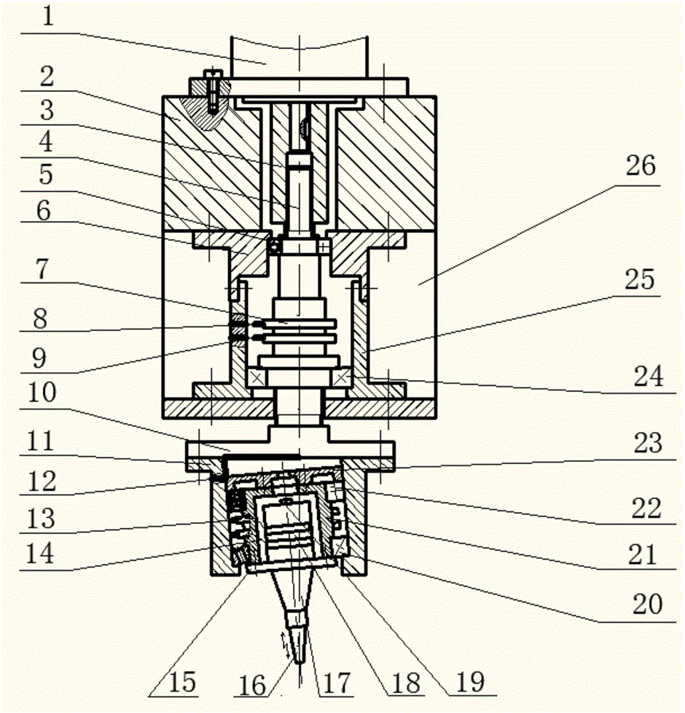
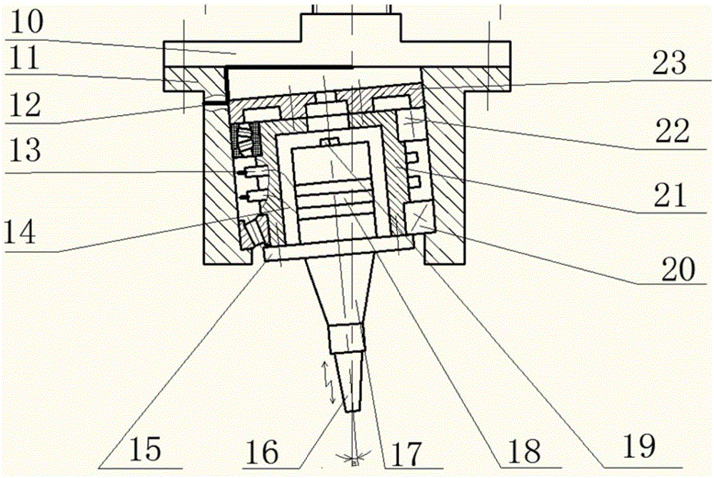
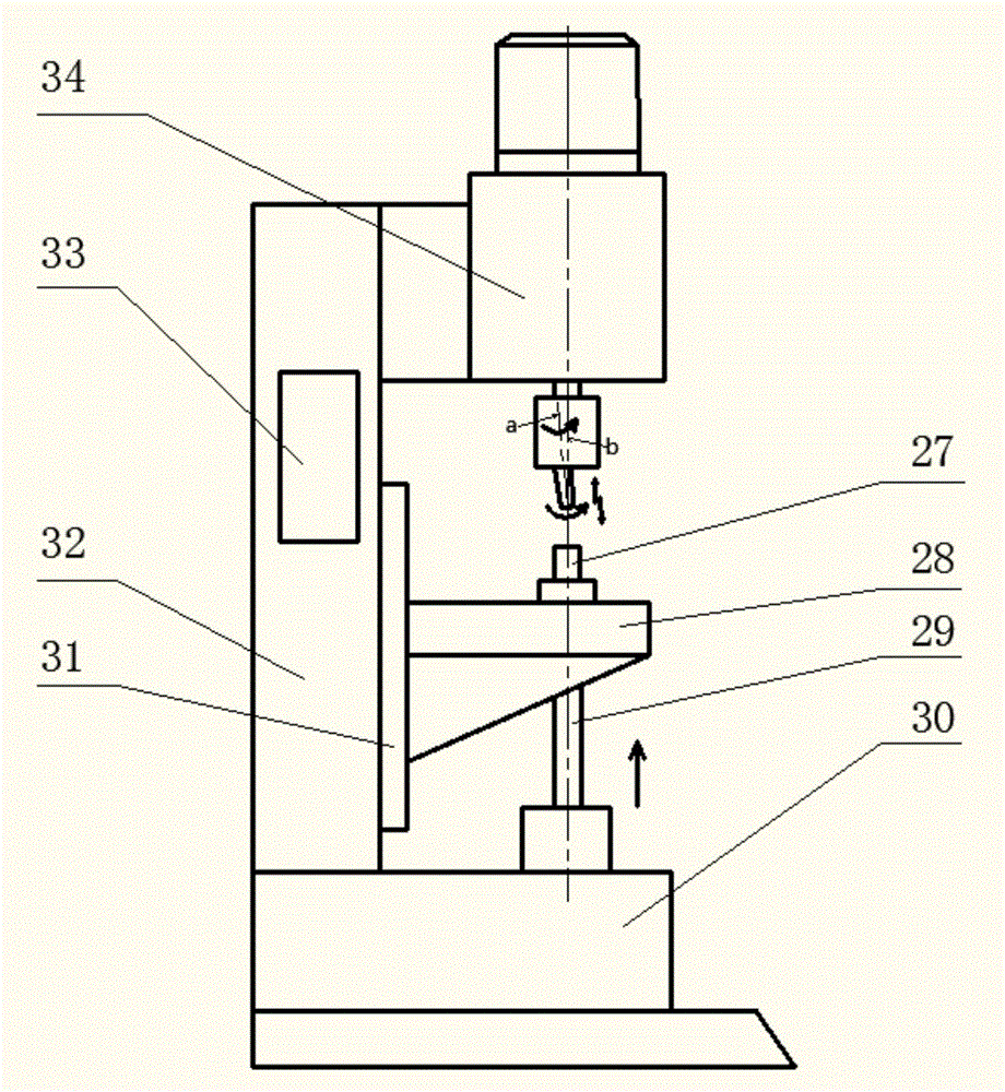
[0025] An ultrasonic riveting machine is composed of a main machine part, a thrust device, a frame part, an upper riveting head and a lower riveting die, such as image 3 shown; the host part includes a rotating device, a collector ring and a vibrating device, such as figure 1 As shown, the rotating device includes a motor 1, a coupling 3, a main shaft 4, a thrust bearing 5, a thrust bearing seat 6, a tapered roller bearing 24 and a tapered roller bearing seat 25, wherein the motor 1 is installed through a set screw On the motor mounting base 2, one end of the main shaft 4 is connected to the motor 1 through the coupling 3, and the other end is connected to the vibrating device (connecting the shaft seat 10) through the screw pair; the vibrating device includes the connecting shaft seat 10, the lower bearing seat 1...


PUM


Abstract

The invention discloses a supersonic vibration spin riveting machine. The supersonic vibration spin riveting machine comprises an upper riveting head (16) which is connected with an amplitude transformer (17). The supersonic vibration spin riveting machine is characterized in that the amplitude transformer (17) is connected with a high frequency transducer (18), and the high frequency transducer (18) is installed in an inner sleeve (21); the inner sleeve (21) is installed in a cylindrical lower bearing pedestal (11) and connected with a connecting end base (10), the connecting end base (10) is connected with the lower end of a main shaft (4), and the upper end of the main shaft (4) is connected with a motor (1); a first electricity collecting ring (7) is installed in the middle of the main shaft (4) and connected with a first wire (9) and an outer guide line through a carbon brush (8) and transmits high frequency electrical signals obtained from an ultrasonic generator; and a second electricity collecting ring (13) transmits the high frequency electrical signals of the first electricity collecting ring (7) to the transducer (18) through a second wire (12), so that the transducer (18) generates high frequency mechanical vibration to drive the amplitude transformer (17) to do high-frequency vibration. By means of the supersonic vibration spin riveting machine, the riveting force can be reduced, and the riveting efficiency can be improved.

Description

technical field [0001] The invention relates to a riveting device, in particular to a riveting device with movement in four directions, in particular to an ultrasonic vibration riveting machine. Background technique [0002] As an important mechanical connection method, riveting is widely used in modern industrial assembly. In recent years, with the development of the aviation industry and material science, the application of aerospace materials represented by titanium alloys has become more and more extensive. A distinctive feature of this type of material is that it is difficult to deform. Traditional riveting technology is riveting titanium alloys and When representing aviation materials, not only the riveting efficiency is low, but also the riveting quality cannot be guaranteed. [0003] The electromagnetic riveting technology proposed to solve the riveting problem of such difficult-to-machine materials belongs to adiabatic shear deformation. Due to the extremely short...

Claims


Application Information

Patent Timeline
Patent Type & Authority Applications(China)
IPC IPC(8): B21J15/12B21J15/38
CPCB21J15/12
Inventor 丁力平陈文亮刘勇王珉陶克梅潘国威黄志祥屈龙强
Owner NANJING UNIV OF AERONAUTICS & ASTRONAUTICS
Why Eureka
Try Eureka