
Clean-up Pneumatic Tank Sampler

A sampler and pneumatic technology, which is applied in the field of tank cleaning-free pneumatic under-tank samplers, can solve the problems such as the inability to directly observe the height of the sampling position in the tank, the large sampling error of the sampling position, waste of financial and material resources, etc., to avoid oil Product pollution and waste, easy operation, variety of effects

Active Publication Date: 2017-09-19
HEBEI CHENXIAO IND AUTOMATION EQUIP CO LTD
View PDF5 Cites 0 Cited by
  • Summary
  • Abstract
  • Description
  • Claims
  • Application Information

AI Technical Summary

Problems solved by technology

The existing defects of the under-tank sampler are: 1) During the installation process of the sampler, the tank needs to be cleared first, and the hot condition in the tank can only be installed and used. The installation period is long; when the tank is cleaned, the tank needs to be removed. The internal medium is cleaned. The general steps of cleaning the tank include oil dischargefumigation→ventilation→reaching the conditions of people entering and hot fire in the tank, then cleaning→rust removal→painting and other processes, and then personnel can enter the tank for installation. Cleaning the tank The steps are complicated, and it takes 15-30 days in the middle, which is time-consuming, laborious, and wastes financial and material resources, which affects normal production; 2) When the internal parts of the storage tank fail, the fault can only be eliminated after the tank is cleaned; 3) In the laboratory analysis In the process, when there is a layered medium in the tank, it is necessary to take a sample per meter, or a sample at a fixed position, the existing sampler under the tank cannot meet the requirements of the test; At that time, petrochemical enterprises implemented the sampling standard of ISO 3170 (GB / T4756-1998) "Manual Sampling Method for Petroleum Liquid Products", requiring the position error to be between ±100mm. The height of the sampling position in the tank cannot be directly observed; 4) The scope of application is narrow, only suitable for certain storage tanks and sampling of certain types of petroleum liquid products

Method used


Image

  • Clean-up Pneumatic Tank Sampler
  • Clean-up Pneumatic Tank Sampler
  • Clean-up Pneumatic Tank Sampler

Examples


Embodiment Construction

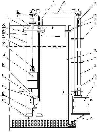
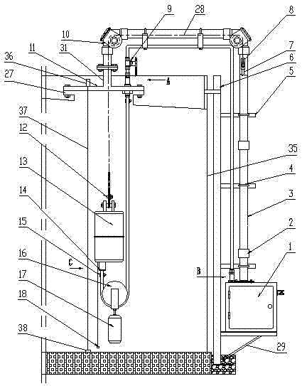
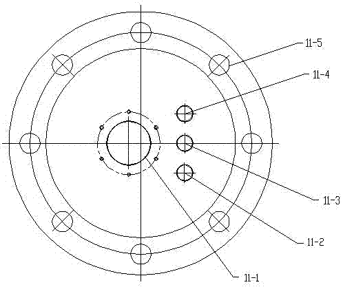
[0041] Such as Figure 1-22 As shown, the tank-free pneumatic type under-tank sampler is composed of an outer part and an inner part of the tank. Connecting flange 11, exhaust valve 30, protection pipe joint 31, intake pipe joint 32, oil outlet pipe joint 33, oil return pipe joint 34, column 6, operation box bracket 29, several support frames 5, operation box part installation 1, protection Pipeline, several U-shaped clips 4, scale code belt 7, steel wire rope 28 and cross connector 8, the oil pipeline outside the tank is composed of intake pipeline 19, oil outlet pipeline 20 with emergency ball valve 9 installed at the upper mouth end, and oil return pipeline 21, the connecting flange 11 is equipped with an exhaust valve 30, and is provided with a protective pipeline installation hole 11-1, an intake pipeline installation hole 11-2, an oil outlet pipeline installation hole 11-3, and an oil return pipeline installation hole 11-4 and several bolt holes 11-5, at the protection ...


PUM


Abstract

A tank-free pneumatic under-tank sampler, which consists of an outer part and an inner part of the tank. When the storage tank is a floating roof tank, the outer part of the tank includes the oil pipeline outside the tank, connecting flanges, exhaust valves, protection Pipe joints, intake pipe joints, oil outlet pipe joints, oil return pipe joints, columns, operation box brackets, several support frames, operation box parts, protection pipelines, several U-shaped clips, scale code belts, steel wire ropes and cross connectors, tanks The external oil pipeline is composed of the intake pipeline, the oil outlet pipeline with an emergency ball valve installed on the upper port, and the oil return pipeline; the inner part of the tank includes the oil pipeline in the tank, 3 hose clamps, the pulley assembly, and submerged sampling Device, wire rope clamp, sampling oil pipe and counterweight, the oil pipeline in the tank is composed of inlet hose, oil outlet hose and return air hose; when the storage tank is a vaulted tank, the outer part of the tank also includes a Tightening device, the inner part of the tank also includes a guide wire and a counterweight iron. It is easy to install, free from tank cleaning, easy to maintain, and accurate in sampling.

Description

technical field [0001] The invention relates to a sampler, in particular to a tank-free pneumatic under-tank sampler. Background technique [0002] At present, in petrochemical production, in order to obtain the performance parameters of the medium in the storage tank, it is necessary to sample and test the liquid stored in the storage tank in time. At present, my country's petrochemical enterprises implement the sampling standard of ISO 3170 (GB / T4756-1998) "Manual Sampling of Petroleum Liquid Products". The sampling operation requires sampling personnel to climb to the top of the tank and use sampling barrels for sampling, which is time-consuming and laborious. When suffering from bad weather or toxic gases volatilized on site, it often threatens the health and even life safety of sampling workers. [0003] As petrochemical companies now have higher and higher requirements for safe and environmentally friendly production and improved working environment for employees, more...

Claims


Application Information

Patent Timeline
Patent Type & Authority Patents(China)
IPC IPC(8): G01N1/14
Inventor 郭文光郭文平
Owner HEBEI CHENXIAO IND AUTOMATION EQUIP CO LTD
Learn More