
Time-domain calibration method for electromagnetic pulse magnetic-field probe

A magnetic field probe and calibration method technology, applied in the direction of measuring electrical variables, measuring devices, instruments, etc., can solve the problems of complicated calibration experiment process, long time consumption, and inability to obtain the time domain transfer function of the pulse probe, so as to achieve simple operation of the calibration work The effect of convenient and convenient time domain calibration

Active Publication Date: 2015-11-25
中国人民解放军63973部队
View PDF9 Cites 17 Cited by
  • Summary
  • Abstract
  • Description
  • Claims
  • Application Information

AI Technical Summary

Problems solved by technology

One measurement can only calibrate the magnetic field probe at a single frequency point, and multiple measurements are required to achieve the calibration of the working frequency band of the magnetic field probe to be tested. The calibration experiment process of this method is complicated and time-consuming, and it is not suitable for the electromagnetic pulse magnetic field probe. domain calibration
[0004] With the expansion of the application field of electromagnetic pulse, the time domain calibration method of electromagnetic pulse probe has been paid more and more attention. System Calibration Method" discloses the method of calibrating the electromagnetic pulse magnetic field probe using a TEM cell. The device uses the standard field method, and the TEM cell has a complex structure, high cost, and inconvenient use.
In 2010, the Proceedings of the Fifteenth National Nuclear Electronics and Nuclear Detection Technology Academic Annual Conference, pages 566-571, "Research on the Calibration Method of Very Low Frequency Electromagnetic Pulse Detectors" discloses the use of bounded wave simulators for the calibration of very low frequency magnetic field probes method, this method only obtains the calibration coefficient of the pulse peak, but cannot obtain the time domain transfer function of the pulse probe, and realizes the full waveform calibration of the pulse time domain

Method used


Image

  • Time-domain calibration method for electromagnetic pulse magnetic-field probe
  • Time-domain calibration method for electromagnetic pulse magnetic-field probe

Examples


Embodiment 1

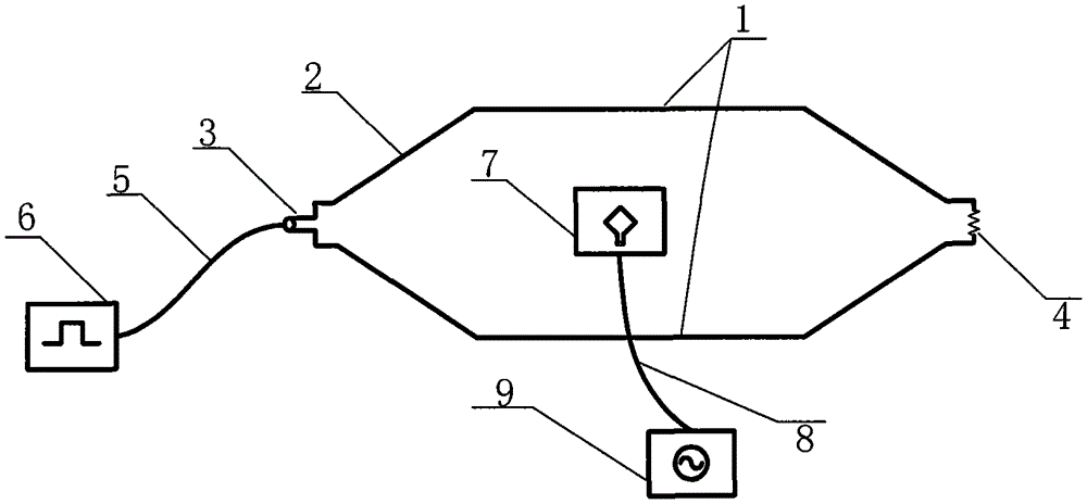
[0028] Such as figure 1 As shown, the time-domain calibration device for the electromagnetic pulse magnetic field probe provided in this embodiment includes a parallel plate transmission line 1, a tapered transition section 2, an adapter 3, a matching load 4, a coaxial cable 5, a pulse signal source 6, and a standard receiver Antenna 7, shielded radio frequency signal line 8, digital oscilloscope 9. During the calibration process, the pulse signal source 6 and the digital oscilloscope 9 are placed outside the parallel plate transmission line 1, and the calibration probe or the standard receiving antenna 7 is placed at the upper and lower and horizontal positions of the parallel section of the parallel plate transmission line 1. / 3 space range. The electromagnetic field in this space meets the requirements of field uniformity in the horizontal direction, the frequency range is 20Hz-2MHz, and the normalized field uniformity is less than 3dB.

[0029] The tapered transition sec...


PUM


Abstract

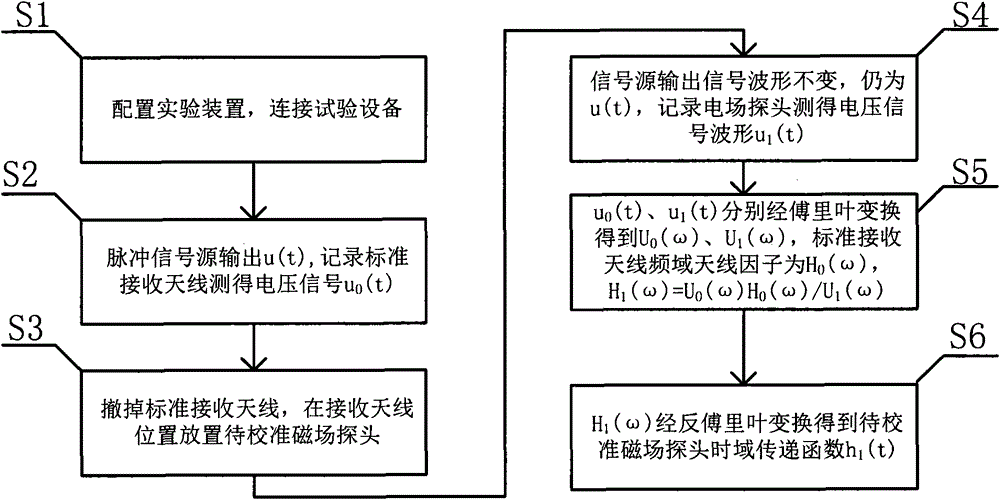
The present invention relates to a time-domain calibration method for an electromagnetic pulse magnetic-field probe. The method is used for calibrating an electromagnetic pulse magnetic-field probe in the time domain. The method comprises the steps of conducting the calibration test in a transmission line parallel-plate working space, connecting the tapered transition section of a parallel-plate transmission line and a pulse signal source with an adapter via coaxial cables, connecting the terminal of the parallel-plate transmission line with a matched load, connecting a digital oscilloscope with a standard antenna or a to-be-calibrated probe via a shielding radio frequency signal line, feeding a pulse voltage signal of the pulse signal source in the parallel-plate transmission line, forming a pulsed magnet field in the transmission line parallel-plate working space, recording a voltage signal waveform measured by the standard receiving antenna or the to-be-calibrated magnetic-field probe by the digital oscilloscope, and processing measured voltage signals according to a certain algorithm to obtain the time-domain transfer function of the to-be-calibrated magnetic-field probe. In this way, the time-domain calibration on the to-be-calibrated magnetic-field probe that is the same with the standard receiving antenna in frequency band can be realized.

Description

technical field [0001] The invention relates to a time-domain calibration method for an electromagnetic pulse magnetic field probe, which belongs to the field of transient electromagnetic pulse magnetic field measurement and provides a calibration method for transient electromagnetic pulse magnetic field measurement equipment. Background technique [0002] The electromagnetic pulse measurement is an important part of the electromagnetic pulse experiment. The electromagnetic pulse measurement needs to obtain the time-domain waveform of the electric field or magnetic field to be measured. Therefore, it is necessary to directly calibrate the probe (equipment) for measuring the electromagnetic pulse electric field or magnetic field in the time domain. [0003] Commonly used magnetic field probe calibration methods are mainly calibrated in the frequency domain. In this method, the signal source outputs a continuous wave signal with a specific amplitude and specific frequency durin...

Claims


Application Information

Patent Timeline
IPC IPC(8): G01R35/00
Inventor 张雪芹李欣梁睿曹保锋范江兵李鹏庞新良马彦
Owner 中国人民解放军63973部队
Learn More