
A field emission device and its manufacturing method

A technology of field emission device and manufacturing method, which is applied in the direction of electrical components, cold cathode manufacturing, electrode system manufacturing, etc., can solve the problems of limited application, achieve the improvement of electron concentration, improve the field enhancement factor and field emission characteristics, and achieve low emission rate effect

Active Publication Date: 2017-10-24
SUZHOU INST OF NANO TECH & NANO BIONICS CHINESE ACEDEMY OF SCI
View PDF3 Cites 0 Cited by
  • Summary
  • Abstract
  • Description
  • Claims
  • Application Information

AI Technical Summary

Problems solved by technology

One-dimensional nanomaterial field emission devices start from carbon nanotube arrays, but the electronic structure of carbon nanotubes limits the application of field emission

Method used


Image

  • A field emission device and its manufacturing method
  • A field emission device and its manufacturing method
  • A field emission device and its manufacturing method

Examples


Embodiment Construction

[0019] Hereinafter, embodiments of the present invention will be described in detail with reference to the accompanying drawings. This invention may, however, be embodied in many different forms and should not be construed as limited to the specific embodiments set forth herein. Rather, the embodiments are provided to explain the principles of the invention and its practical application, thereby enabling others skilled in the art to understand the invention for various embodiments and with various modifications as are suited to particular intended uses.

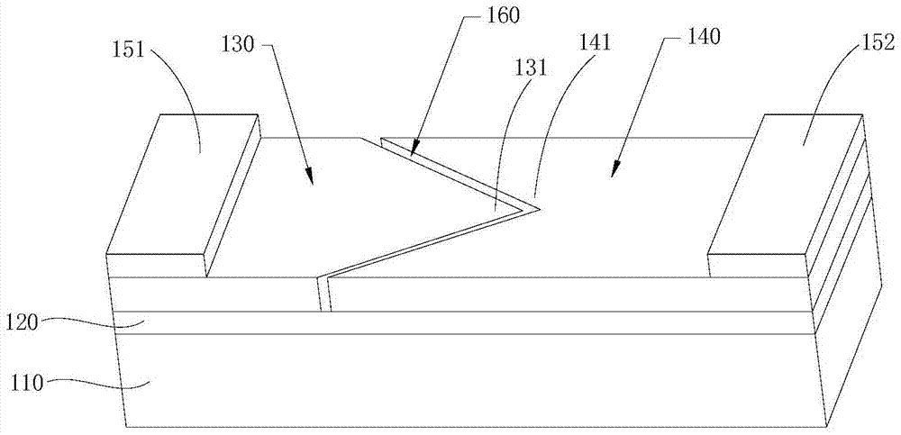
[0020] figure 1 A perspective view of a field emission device according to an embodiment of the present invention.

[0021] refer to figure 1 A field emission device according to an embodiment of the present invention includes a substrate 110, a buffer layer 120 disposed on the substrate 110, an emitter layer 130 and a collector layer 140 respectively disposed on both ends of the buffer layer 120, and The first metal elect...


PUM


Abstract

The invention discloses a field emission device, which comprises a substrate, a buffer layer arranged on the substrate, an emitter layer and a collector layer respectively arranged at both ends of the buffer layer, The metal electrode layer, wherein there is a channel between the emitter layer and the collector layer. The invention also discloses a manufacturing method of the field emission device. The field emission device and its manufacturing method of the invention can increase the field enhancement factor and the field emission characteristics.

Description

technical field [0001] The invention belongs to the technical field of semiconductors, and in particular relates to a field emission device and a manufacturing method thereof. Background technique [0002] Due to the advantages of small size, long life, easy integration, low energy consumption, high reliability, low noise and low operating voltage, semiconductor devices have replaced vacuum electronic devices in almost every application field, but vacuum electronic devices are in a vacuum due to electron transport Complete, its operating frequency is higher than that of solid-state devices, and it can work at high frequency and high power at the same time. Therefore, vacuum microelectronic devices still have great application prospects in high-power high-frequency (for example, in radar, communication and electronic countermeasures, etc.), special displays and high-fidelity audio equipment. [0003] The core part of the vacuum electronic device is the emitting cathode. The ...

Claims


Application Information

Patent Timeline
Patent Type & Authority Patents(China)
IPC IPC(8): H01J1/304H01J9/02
CPCH01J1/304
Inventor 赵德胜张宝顺
Owner SUZHOU INST OF NANO TECH & NANO BIONICS CHINESE ACEDEMY OF SCI
Learn More