Self-aligning sintering clamp of semiconductor laser tube core and tube core sintering method

A laser and semiconductor technology, which is applied in the direction of semiconductor lasers, lasers, laser components, etc., can solve the problems of reducing the reliability of the sintering pass rate, the difficulty of processing and assembling precision parts, reducing the sintering yield and the quality of the spot, etc., to reduce Sintering cavity, low production cost, solve the effect of low luminous efficiency

Inactive Publication Date: 2015-11-25
Shandong Huaguang Optoelectronics Co. Ltd.
View PDF6 Cites 8 Cited by
  • Summary
  • Abstract
  • Description
  • Claims
  • Application Information

AI Technical Summary

Problems solved by technology

The disadvantage of this method is that the heat sink needs to be accurately placed in the corresponding position of the base fixing groove under the microscope to ensure that it is facing the pressure pin; and the core is pressed by the gravity of the pressure pin. In the furnace and during high-temperature sintering, the pressure pin may be displaced due to vibration and melting of the solder, causing the die to shift, reducing the sintering pass rate and the reliability of the laser
The disadvantage of this method is that it is necessary to place heat sinks, tube cores and drop pressing pins under the microscope, which is inconvenient to use and low in efficiency; and there are many parts in the whole device, it is difficult to process and assemble the precision parts required, and the manufacturing cost High, not suitable for batch sintering
The fixture needs to position and place the laser packaged on the sub-heat sink under the observation of a microscope. Due to the lack of corresponding positioning devices, self-alignment cannot be achieved, and the operation is inconvenient; It is inclined to the bottom surface, which may cause the sliding displacement of the laser die when touching the laser, which will cause the sintered laser to shift, reducing the sintering yield and spot quality

Method used


Image

  • Self-aligning sintering clamp of semiconductor laser tube core and tube core sintering method
  • Self-aligning sintering clamp of semiconductor laser tube core and tube core sintering method
  • Self-aligning sintering clamp of semiconductor laser tube core and tube core sintering method

Examples


Embodiment 1

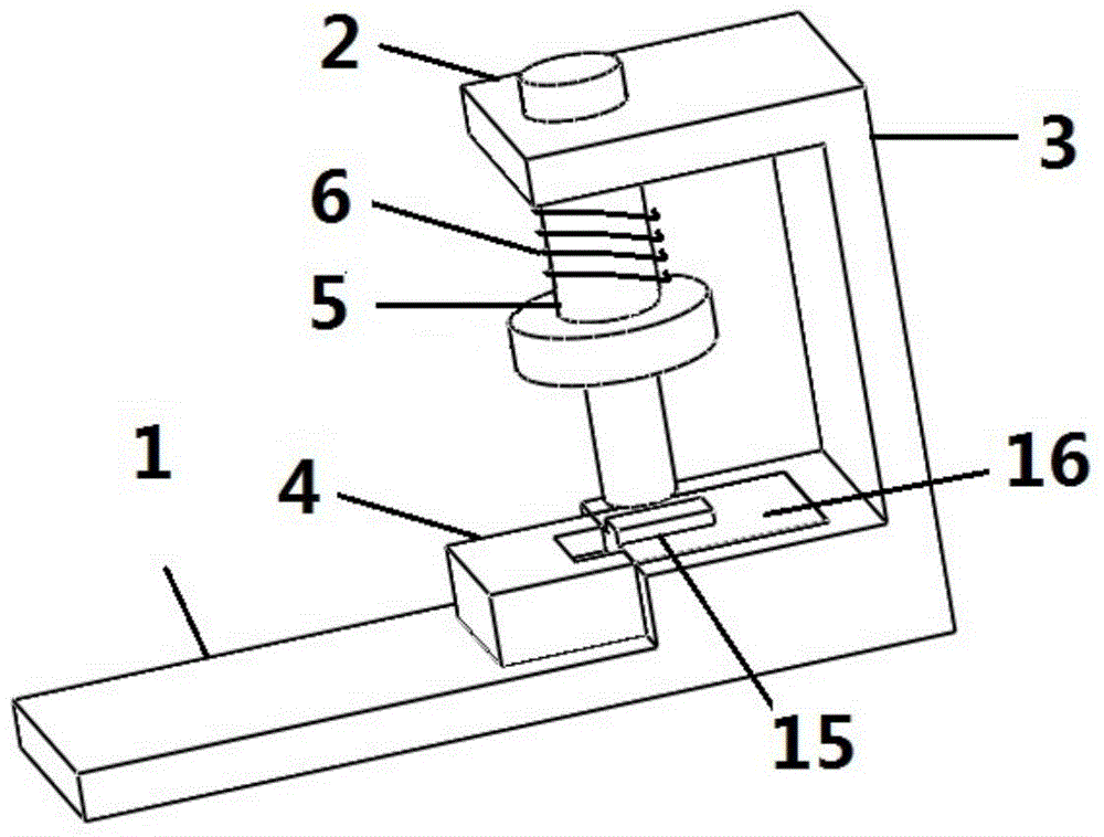
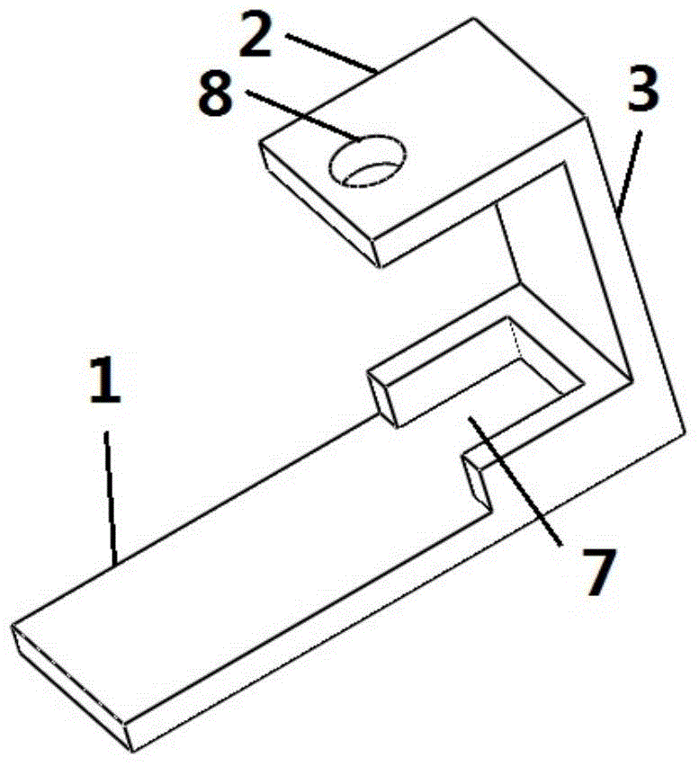
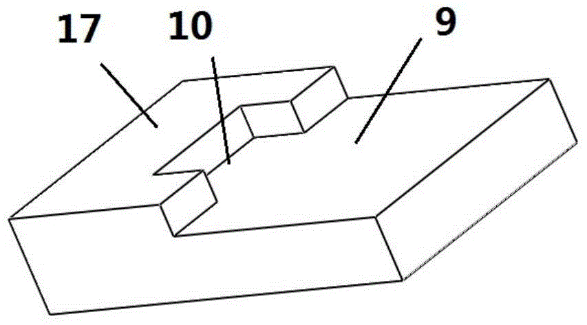
[0041] Self-aligned sintering fixtures for semiconductor laser dies, such as figure 1 As shown, it includes a bracket, an alignment base 4, a pressing post and a spring 6. The bracket, such as figure 2 As shown, it includes a bottom support 1, a cantilever 2 and a connecting arm 3. There is a positioning slot 7 on the bottom support 1 that is compatible with the alignment base 4. The positioning slot 7 is a rectangular groove with one side open, so that the alignment The position base 4 can move in the positioning card slot 7 and the side is attached to the inner wall of the card slot; the counter base 4 is rectangular or square stepped, such as image 3 As shown, there is a first plane 17 and a second plane (the lower plane of the step), the first plane 17 is higher than the second plane, the second plane is the heat sink platform 9, and the size of the heat sink platform 9 is suitable for the heat sink 16 Matching, so that the die 15 on the heat sink 16 can be aligned wit...

Embodiment 2

[0046] Utilize the self-aligned sintering fixture of embodiment 1 to carry out the method for semiconductor laser tube core sintering, the steps are as follows:

[0047] (1) Place the heat sink with solder on the heat sink mounting table of the alignment base, and place the semiconductor laser die on the solder of the heat sink with an adsorption machine under a microscope;

[0048] (2) Put the matching spring on the pressure column, insert the upper end of the pressure column into the pressure column guide hole on the cantilever of the bracket and lift it up;

[0049] (3) Insert the alignment base with the heat sink and the die into the positioning slot of the bottom support of the bracket, and push it to the end;

[0050] (4) Lower the pressure column so that it is facing the laser die and press it tightly to complete the setting of the fixture;

[0051] (5) Repeat the above steps (1) to (4) to set up several other identical fixtures to hold the heat sink and die; The shel...

Embodiment 3

[0053] As described in Example 1, the difference is that the structure of the alignment base is as follows Image 6 As shown, the alignment base has a first plane 17, a second plane 18 and a third plane 19, the first plane 17 is higher than the second plane 18, and the second plane 18 is a heat sink mounting platform suitable for the size of the heat sink Matching, the second plane 18 is higher than the third plane 19, and the size of the third plane 19 is adapted to the positioning slot 7. For heat sinks with smaller dimensions.


PUM


Abstract

The invention relates to a self-aligning sintering clamp of a semiconductor laser tube core and a tube core sintering method. The self-aligning sintering clamp comprises a bracket, an alignment base, a compression column and a spring, wherein the bracket is provided with a bottom support seat and a cantilever; a positioning clamping groove matched with the alignment base is formed in the bottom support seat; a compression column guide hole is formed in the cantilever; the spring sleeves the upper part of the compression column; a heat sink carrying table is arranged on the alignment base; and the tube core on the heat sink can be rightly aligned at the lower end of the compression column when the alignment base is completely pushed into the positioning clamping groove, so that the compression column can be pressed on the tube core under the elasticity of the spring. The invention further provides a method for sintering the semiconductor laser tube core by the clamp. The clamp provided by the invention is simple in structure; self-aligning can be realized; the overall clamp can be conveniently arranged in a nitrogen protective casing; oxidation of solder is effectively prevented during high-temperature sintering; and fast and massive sintering of the tube core and the heat sink of the semiconductor laser is realized.

Description

technical field [0001] The invention relates to a self-aligning sintering jig for semiconductor laser tube cores and a using method thereof, belonging to the technical field of semiconductor laser tube core sintering. Background technique [0002] Semiconductor lasers have the advantages of small size, light weight, high electro-optical conversion efficiency, long life and high reliability, and are gradually replacing the traditional gas and solid-state lasers in the application market. The application gradually expands. When the semiconductor laser is working, the waste heat generated by the die needs to be discharged in time, otherwise it will cause the device to overheat and cause the laser to fail. Therefore, the widely used technical solution is to sinter the semiconductor laser die onto a heat sink with strong heat dissipation capability, and effectively evacuate the heat generated by the die through the heat sink. The connection between the heat sink and the die nee...

Claims


Application Information

Patent Timeline
IPC IPC(8): H01S5/022H01S5/024
Inventor 杨扬孙素娟李沛旭苏建徐现刚
Owner Shandong Huaguang Optoelectronics Co. Ltd.
Why Eureka
Try Eureka