Asynchronous constant speed wind turbine system for micro grid and working method thereof

A technology for wind turbines and working methods, which is applied in wind power generation, single grid parallel feeding arrangement, reactive power compensation, etc., can solve the problem that it is difficult to achieve low voltage ride through grid reactive power support, the windward angle of the blades cannot be changed accordingly, and the influence Microgrid isolated grid stability and other issues, to achieve the effects of smoothing wind power fluctuations, improving transient voltage stability levels, and improving voltage stability levels

Inactive Publication Date: 2015-11-25
ELECTRIC POWER RESEARCH INSTITUTE OF STATE GRID SHANDONG ELECTRIC POWER COMPANY +1
View PDF4 Cites 11 Cited by
  • Summary
  • Abstract
  • Description
  • Claims
  • Application Information

AI Technical Summary

Problems solved by technology

[0003] The traditional asynchronous wind turbines that were put into production in the early stage have shortcomings such as non-adjustable power and weak reactive power support capability. The requirements of modern power grids for the operation of wind turbines are controllable power and low voltage ride-through capabilities.
At present, there are still a certain number of early-stage asynchronous wind turbines in some islands and remote areas. When the wind speed changes, the windward angle of the blades cannot change accordingly, unlike double-fed induction wind turbines and permanent magnet wind turbines. Reactive power regulation by changing the magnitude and phase of the excitation current
When this type of wind turbine is included in the microgrid system, it is difficult for the wind turbine to realize low-voltage ride-through and reactive power support to the grid during low-voltage ride-through, which affects the stability of the isolated grid operation of the microgrid, and in severe cases causes microgrid System crashes, damage to electrical equipment

Method used


Image

  • Asynchronous constant speed wind turbine system for micro grid and working method thereof
  • Asynchronous constant speed wind turbine system for micro grid and working method thereof
  • Asynchronous constant speed wind turbine system for micro grid and working method thereof

Examples


Embodiment Construction

[0031] Below in conjunction with accompanying drawing and embodiment the present invention will be further described:

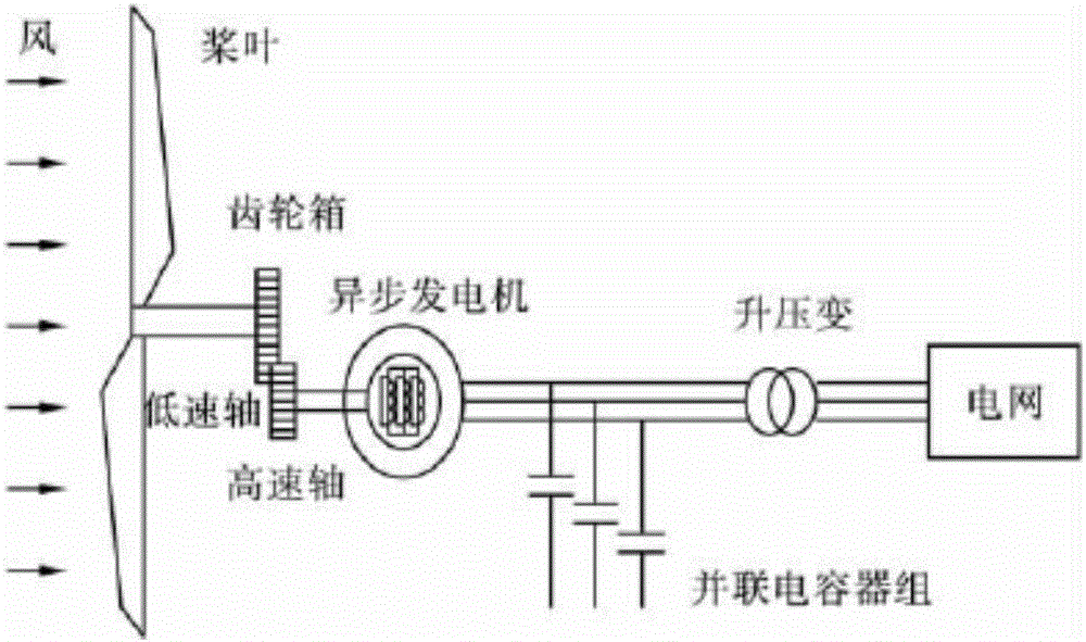
[0032] Such as figure 1 As shown, taking the squirrel-cage asynchronous constant-speed wind turbine as an example, the asynchronous constant-speed wind turbine is mainly composed of blades, gearboxes, ordinary asynchronous generators and step-up transformers. In the squirrel-cage asynchronous constant-speed wind turbine, the pitch angle and speed of the rated speed of the generator are fixed. While generating active power, it also needs to consume reactive power, usually by installing a capacitor.

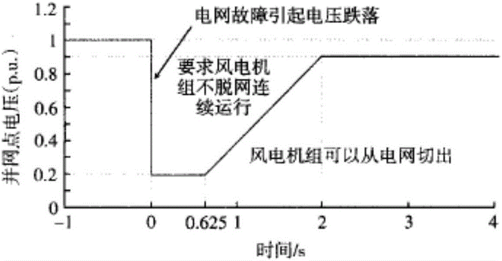
[0033] figure 2 It is a schematic diagram of low-voltage ride-through capability requirements of wind turbines. Under the conditions of phase-to-phase short-circuit faults, two-phase short-circuit faults, and single-phase-to-ground short-circuit faults, the wind turbines in the wind farm can guarantee that the grid point voltage drops to 20% of the rated voltage...


PUM


Abstract

The invention discloses an asynchronous constant speed wind turbine system for a micro grid and a working method thereof. The system comprises a wind wheel, a gear box and an asynchronous generator connected in sequence. The asynchronous constant speed wind turbine system for the micro grid also comprises a wind power-side circuit breaker, and one end of the wind power-side circuit breaker is connected with a stator side of the asynchronous constant speed wind turbines and the other end is connected with an isolation transformer. The isolation transformer is connected with an AC/DC/AC converter, the AC/DC/AC converter is connected onto a wind turbine substation via a grid-side circuit breaker, the wind turbine substation is connected onto an AC bus, and a grid-connected circuit breaker is also arranged between the AC bus and the grid. Wind power fluctuations are stabilized, power balancing and stability of the overall system when the micro grid works are maintained.

Description

technical field [0001] The invention belongs to the field of wind power generation, and in particular relates to an asynchronous constant-speed wind turbine system for a microgrid and a working method thereof. Background technique [0002] The "Technical Regulations for Connecting Wind Farms to Power Systems" puts forward the following requirements: Under the conditions of grid phase short circuit faults, two phase short circuit faults and single phase ground short circuit faults, the wind turbines in the wind farm have a voltage drop to 20% of the grid point. At rated voltage, it can guarantee the ability to run continuously for 625ms without going off-grid; when the voltage at the grid-connected point of the wind farm can recover to 90% of the rated voltage within 2s after a drop, the wind turbines in the wind farm can guarantee continuous operation without going off-grid. [0003] The traditional asynchronous wind turbines that were put into production in the early stage ...

Claims


Application Information

Patent Timeline
Patent Type & Authority Applications(China)
IPC IPC(8): H02J3/38H02J3/18
CPCY02E10/76Y02E40/30
Inventor 李广磊孙树敏石鑫李笋马杰程艳王昭鑫于芃韩德顺袁帅颜勇
Owner ELECTRIC POWER RESEARCH INSTITUTE OF STATE GRID SHANDONG ELECTRIC POWER COMPANY
Why Eureka
Try Eureka