Intravascular ultrasonic focusing method, focusing diagnostic device and focusing energy transducer

An ultrasonic transducer and ultrasonic focusing technology, applied in catheters, surgery, etc., can solve the problem of detection signal-to-noise ratio reduction, achieve the effects of reducing scattering intensity, reducing scattering volume dv, and improving clarity

Active Publication Date: 2015-12-02
上海爱声生物医疗科技有限公司 +1
View PDF6 Cites 23 Cited by
  • Summary
  • Abstract
  • Description
  • Claims
  • Application Information

AI Technical Summary

Problems solved by technology

[0004] Aiming at the problems existing in the above-mentioned prior art, the present invention proposes an intravascular ultrasonic focusing method, a focusing diagnostic instrument and a focusing transducer, and utilizes the ultrasonic focusing technology to significantly improve the resolution of the vascular diagnostic instrument and solve the problems of the prior art. In order to improve the resolution, the detection signal-to-noise ratio is reduced

Method used


Image

  • Intravascular ultrasonic focusing method, focusing diagnostic device and focusing energy transducer
  • Intravascular ultrasonic focusing method, focusing diagnostic device and focusing energy transducer
  • Intravascular ultrasonic focusing method, focusing diagnostic device and focusing energy transducer

Examples


Embodiment 1

[0065] Example 1: Intravascular Ultrasound Focusing Transducer Using Overall Acoustic Structure Focusing Technology

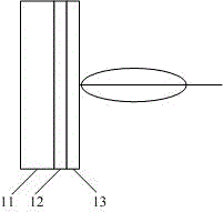
[0066] Such as Figure 4 Shown is a schematic diagram of the ultrasonic focusing transducer of this embodiment, which includes a backing layer 11, a piezoelectric layer 12, and an acoustic matching layer 13 closely connected in sequence, wherein: the backing layer 11, the piezoelectric layer 12, and the acoustic matching layer The layers 13 all have mechanical curved surfaces, and the radii of curvature of the three can be calculated and set according to the requirements of the focused sound field. The focus factor K is defined as the ratio of the focal length f to the transducer aperture d, ie: K=f / d. Given the focus factor K and the focal length f, the size of the aperture d can be calculated.

Embodiment 2

[0067] Example 2: Intravascular Ultrasound Focusing Transducer Using Acoustic Lens Focusing Technology

[0068] Such as Figure 5 Shown is a schematic diagram of the ultrasonic focusing transducer of this embodiment, which includes a backing layer 11, a piezoelectric layer 12, an acoustic matching layer 13, and an acoustic lens 14 closely connected in sequence, wherein the acoustic lens 4 has a mechanically curved surface, and its The radius of curvature can be calculated and set according to the requirements of the focused sound field.

[0069] The acoustic lens 14 can be a plano-convex lens or a plano-concave lens, which is determined according to the sound velocity of the lens material. For lens materials whose sound velocity is lower than that of the medium, it is a plano-convex lens, such as Figure 5 Shown by the dotted line in the middle; for the lens material whose sound velocity is higher than the sound velocity of the medium, it is a plano-concave lens, such as F...

Embodiment 3

[0070] Example 3: Intravascular Ultrasound Focusing Transducer Using Electronic Focusing Technology

[0071] Such as Figure 6 Shown is a schematic diagram of the ultrasonic focusing transducer of this embodiment, which includes a plurality of ultrasonic transducing units and a plurality of delay circuits T, each ultrasonic transducing unit corresponds to a delay circuit T,

[0072] In this embodiment, five concentric square ring transducer units are taken as an example, the left view of which is as follows Figure 7 As shown, respectively marked as e1,...e5, the time for the sound wave to reach each ultrasonic transducer unit from point F in the free sound field is different. Therefore, the total received signal is the superposition of signals of different phases, and the output signal cannot be the maximum. The output terminal of each ultrasonic transducer unit is connected with a delay circuit to compensate the time difference caused by the sound path difference of the so...


PUM


Abstract

The invention discloses an intravascular ultrasonic focusing method, focusing diagnostic device and focusing energy transducer. The intravascular ultrasonic focusing method comprises: sending an intravascular ultrasonic focusing diagnostic device to a far-end of a site of lesion; emittingultrasonic signals at 360 DEG to the inside of a blood vessel. The intravascular ultrasonic focusing diagnostic device includes an ultrasonic catheter, awithdrawing/drive apparatus and anelectronic imaging system. The front end of the ultrasonic catheter is provided with the intravascular ultrasonic focusing energy transducer. The rear end of the ultrasonic catheter is connected to the withdraw/drive apparatus which is connected to the electronic imaging system. The intravascular ultrasonic focusing energy transducer includes ultrasonic energy transducer units and a focusing unit. The ultrasonic energy transducer units serve to emitultrasonic signals and receive an ultrasonic signal that is reflected. The focusing unit serves to focus the ultrasonic signalemitted by the ultrasonic energy transducer unit. According to the invention, the resolution of the diagnostic device is increased and the signal to noise ratio of the imaging of the diagnostic deviceis increasedby using intravascular ultrasonic focusing technology, so that the diagnosis precision is increased.

Description

technical field [0001] The invention relates to an intravascular ultrasonic diagnostic instrument, in particular to an intravascular ultrasonic focusing method, a focusing diagnostic instrument and a focusing transducer. Background technique [0002] Intravascular ultrasonic diagnostic instrument is the most effective ultrasonic diagnostic instrument for diagnosing blockage of cardiovascular or peripheral blood vessels; it is known as the "gold standard" for analyzing blockage of cardiovascular or peripheral blood vessels. It can quantitatively detect the distance position and range size of the blocking section and so on. Since the vascular wall is composed of tunica intima, tunica media and adventitia from the luminal surface, the intravascular ultrasonic diagnostic instrument can also be used to analyze the lesions of the vascular wall. [0003] The inner diameter of blood vessels only ranges from millimeters to centimeters. In order to analyze vascular blockage and lesi...

Claims


Application Information

Patent Timeline
Patent Type & Authority Applications(China)
IPC IPC(8): A61B8/12
Inventor 袁建人陈友伟马晓雯曹培杰
Owner 上海爱声生物医疗科技有限公司
Why Eureka
Try Eureka