Automatic tracking monitoring system based on machine vision and target pellet and gas-filled tube assembly monitoring method implemented through adoption of system
An automatic tracking and machine vision technology, applied in the direction of using optical devices, measuring devices, instruments, etc., can solve the problems of low assembly accuracy and low assembly efficiency, and achieve the effects of excellent alignment accuracy, assembly accuracy and speed improvement
- Summary
- Abstract
- Description
- Claims
- Application Information
AI Technical Summary
Problems solved by technology
Method used
Image

Examples
specific Embodiment approach 1
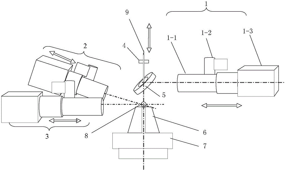
[0027] Specific implementation mode one: see figure 1 Describe this embodiment, a machine vision-based automatic tracking and monitoring system described in this embodiment, which includes a first micro-vision system 1, a second micro-vision system 2, a third micro-vision system 3, an air tube Fine-tuning auxiliary clamping piece 4, reflector 5, negative pressure adsorption head 6, and pellet micro-adjustment platform 7;
[0028] The structure of the first micro vision system 1, the second micro vision system 2 and the third micro vision system 3 is exactly the same, the negative pressure adsorption head 6 is placed on the target pellet micro-adjustment platform 7, the negative pressure adsorption head 6 is used to adsorb the target pellet 8,
[0029] The center of reflecting mirror 5 is provided with through hole, and gas-filled tube 9 is positioned at the top of reflecting mirror 5, and passes through the through hole of reflecting mirror 5, and reflecting mirror 5 forms 45...
specific Embodiment approach 2
[0037] Specific embodiment two: the difference between this embodiment and the automatic tracking and monitoring system based on machine vision described in specific embodiment one is that the diameter of the mirror 5 is 20 mm, and the diameter of the through hole on the mirror 5 is 3mm.
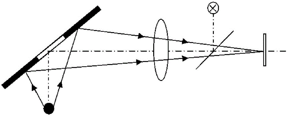
[0038] In this embodiment, since the reflector is hollow and at an angle of 45 degrees to the horizontal, in order to ensure that the inflatable tube can pass through smoothly while reducing the loss of light energy, it is necessary to analyze and calculate the influence of the existence of the through hole on the imaging of the reflector. In the known microscope The size of the mirror and the size of the opening of the mirror can be calculated from the numerical aperture and the distance of the mirror relative to the target.
specific Embodiment approach 3
[0039] Embodiment 3: The difference between this embodiment and the machine vision-based automatic tracking and monitoring system described in Embodiment 1 is that the first micro vision system 1, the second micro vision system 2 and the first micro vision system The three microscopic vision systems 3 are all realized by using a 10x microscopic objective lens 1-1, a coaxial lighting source 1-2, a CCD camera 1-3, and a focusing electric translation stage.
[0040] In this embodiment, the point light source in the microscopic vision system is used as a coaxial light source through the light source socket of the microscope lens, and illuminates the upper side of the target pill through a 45-degree reflector to provide illumination for the on-road camera, so that the CCD can accurately monitor the outline of the target pill and the gas-filled tube. Clear imaging, each microscopic vision system realizes precise position adjustment through the electric focusing platform.
[0041] Al...
PUM
| Property | Measurement | Unit |
|---|---|---|
| Diameter | aaaaa | aaaaa |
| Diameter | aaaaa | aaaaa |
Abstract
Description
Claims
Application Information
 - R&D
- Intellectual Property
- Life Sciences
- Materials
- Tech Scout
- Unparalleled Data Quality
- Higher Quality Content
- 60% Fewer Hallucinations
Browse by: Latest US Patents, China's latest patents, Technical Efficacy Thesaurus, Application Domain, Technology Topic, Popular Technical Reports.
© 2025 PatSnap. All rights reserved.Legal|Privacy policy|Modern Slavery Act Transparency Statement|Sitemap|About US| Contact US: help@patsnap.com