Pumped storage power station

A pumped-storage power station and pool technology, which is applied in the directions of hydropower generation, engine components, machines/engines, etc., can solve the problems of large drop between upper and lower reservoirs, vulnerability to floods, droughts, and large occupied area, reaching the height of the water surface. The effect of small difference, cost reduction and high kinetic energy

Active Publication Date: 2015-12-09
张文庆
View PDF10 Cites 2 Cited by
  • Summary
  • Abstract
  • Description
  • Claims
  • Application Information

AI Technical Summary

Problems solved by technology

[0004] First, the dam needs to be built, the location is remote, the project volume is large, the power grid needs to be erected, and the cost is high;
[0005] Second, the site selection has limitations and occupies a large area, and the surrounding area of ​​the dam must have a solid foundation;
[0006] Third, the drop between the upper and lower reservoirs should be large;
[0007] Fourth, pumping water from the lower reservoir to the upper reservoir has high lift, high power consumption, low efficiency, and a long cycle from pumping water to generating electricity;
[0008] Fifth, it is easily affected by floods, droughts, etc., and has a certain impact on the natural environment;
[0009] Sixth, during the entire operation process, part of the energy will be lost during conversion, which will not increase the power generation, and can only use the price difference of electric energy to realize profits

Method used


Image

  • Pumped storage power station
  • Pumped storage power station
  • Pumped storage power station

Examples


Embodiment 1

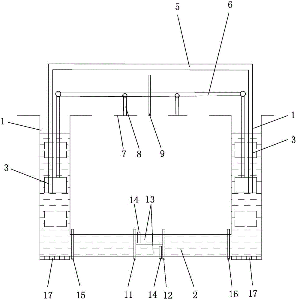
[0045] Embodiment 1: see figure 1 —4:

[0046] A pumped-storage power station, including two transmission power floating body pools 1 arranged at intervals, and the two transmission power floating body pools 1 are connected to 2 through more than two water flow channels. In this embodiment, there are three channels, one for standby, and another The two paths meet the requirement of being discharged from one power transmission floating body pool 1 to the other power transmission floating body pool 1 within a set time. Both transmission power floating body pools 1 are provided with transmission power floating body 3, and the area of ​​transmission power floating body 3 can be set to 1 / 2 of the area of ​​transmission power floating body pool 1, allowing the existence of left-right deviation. A liquid ballast tank 4 is arranged in the transmission power floating body 3, and the liquid ballast tank 4 is connected by an inlet and outlet pipe 5, and the inlet and outlet pipe 5 is used...

Embodiment 2

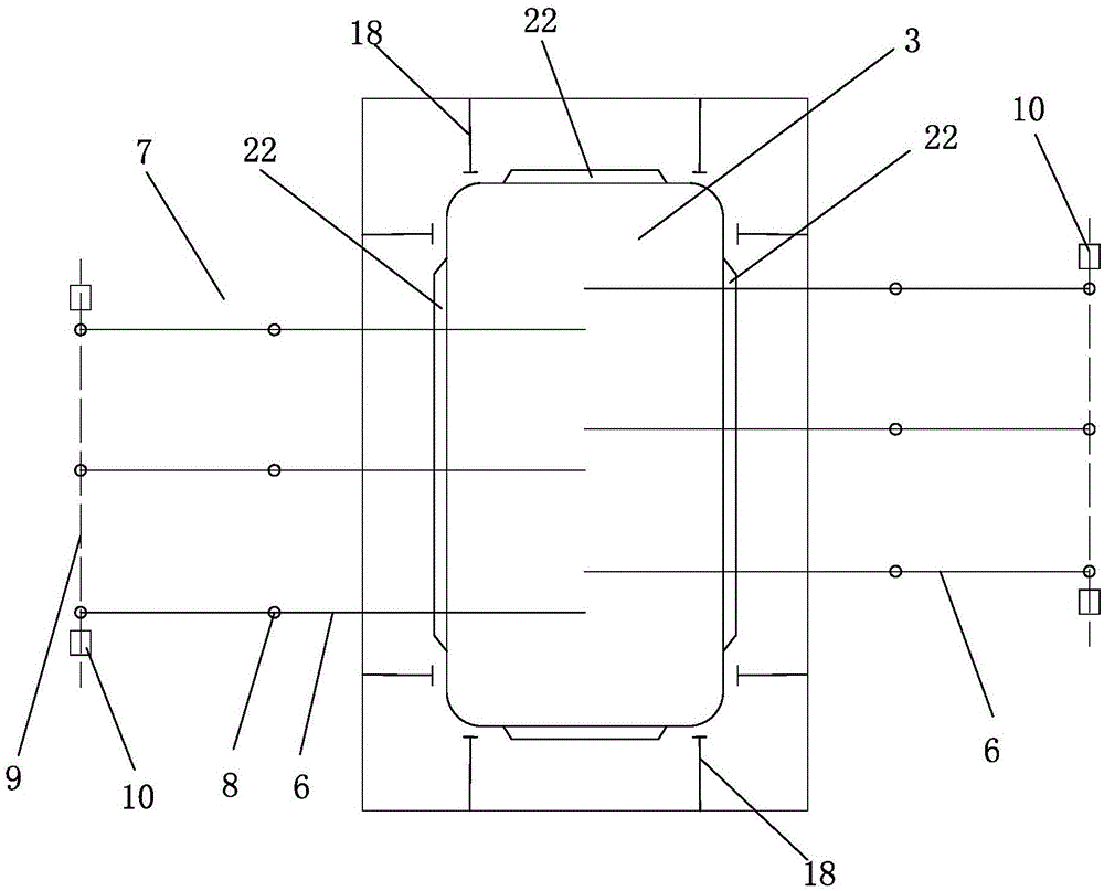
[0076] Example 2: see image 3 -7:

[0077] The difference between this embodiment and Embodiment 1 is that the drive of the generator is driven by a lever connected to the work floating body.

[0078] Rod drive:

[0079] A pumped storage power station, including two groups of pools arranged at intervals, each group of pools includes a power transmission floating body pool 1 and more than one work floating body pool 23, in this embodiment, each power transmission floating body pool 1 corresponds to two working Work floating body pool 23. The specific quantity of work floating body pool 23 can be designed according to actual conditions. The two transmission power floating body pools 1 are connected through more than two water flow channels 2, and the transmission power floating body pools 1 of each group are connected with each work floating body pool 23 through more than two water flow channels 24. In this implementation For example, three water flow passages 24 are set, o...

Embodiment 3

[0106] Embodiment 3: see Figure 8 :

[0107] In this embodiment, the functions of Embodiments 2 and 3 are combined, and at the same time, the power transmission floating body and the work floating body are driven to generate electricity.

[0108] Working principle of the present invention:

[0109] 1. Open the on-off valve (i.e. 28, 29 in Embodiment 2), fill up the ballast water in the fixed ballast tanks of the two transmission power floating bodies 3, and the transmission power floating body 3 is arranged in the middle of the pool;

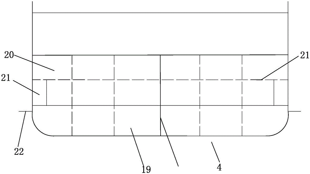
[0110] The ballast water in the ballast tank 20 is adjusted by using one of the transmission power floating bodies (set as A floating body) to adjust the ballast water of the ballast tank 20, so that the draft of the A floating body increases and sinks, so that the transmission power floating body pool 1 where the A floating body is located (set For the water level of A tank) to rise, adjust the cabin pressure to the set height;

[0111] Use...


PUM


Abstract

The invention belongs to the technical field of generating sets, in particular to a pumped storage power station. The pumped storage power station adopts the structure that two power transmission floating body water tanks are communicated with each other through two or more water flow passages; power transmission floating bodies are arranged in both the power transmission floating body water tanks; liquid ballast chambers are arranged in the power transmission floating bodies, and are communicated with one another through water feed / drainage pipelines; an on-off valve is arranged on each water flow passage; water is fed into and drained from the power transmission floating body water tanks through a feed pump and a drainage pump; two power transmission floating bodies are connected with one end of a corresponding lever; the other ends of the levers are connected with a connecting rod; one end of the connecting rod is connected with a generator through a booster engine, or two ends of the connecting rod are connected with generators through booster engines respectively; water level variation in the power transmission floating body water tanks drives the levers to swing around a fulcrum, so as to drive the connecting rod to work and further drive the generator(s) to generate power. The pumped storage power station has the advantages that the efficiency is high; the operation is simple; the application is wide in range and free from limitation of districts; the operation is safe and reliable.

Description

Technical field: [0001] The invention belongs to the technical field of power generation devices, in particular to a pumped storage power station. Background technique: [0002] Electric energy refers to the ability of electricity to do work (that is, generate energy) in various forms. Electric energy is widely used in various fields such as power, lighting, metallurgy, chemistry, textiles, communication, broadcasting, etc. It is the main driving force for the development of science and technology and the leap of the national economy. At the same time, electric energy also brings great convenience to people's life. In daily life, electricity is also inseparable. Electricity is currently the most scarce. At present, thermal power generation is still used more. Thermal power generation generally refers to the general term for the method of using the heat generated by the combustion of fuels such as oil, coal, and natural gas to heat water, turning the water into high-tempe...

Claims


Application Information

Patent Timeline
Patent Type & Authority Applications(China)
IPC IPC(8): F03B17/02F03B13/00
CPCY02E10/20
Inventor 张文庆
Owner 张文庆
Why Eureka
Try Eureka