
Copper-plated steel wire hot air circulation drying system

A technology of hot air circulation and drying system, which is applied in drying, drying machines, drying solid materials, etc., can solve the problems of unguaranteed drying quality and increased energy consumption, and achieve highly stable drying quality, high heat utilization rate, The simple effect of the system

Active Publication Date: 2017-08-08
长春航天安可工业有限公司
View PDF7 Cites 0 Cited by
  • Summary
  • Abstract
  • Description
  • Claims
  • Application Information

AI Technical Summary

Problems solved by technology

A condensing device is added to the hot air circulation system. Although the water mist is condensed into liquid water and discharged, the circulating air components are also cooled at the same time, which increases energy consumption; the discharged part of the high-humidity and high-temperature hot gas supplements the low-humidity cold air, and there is also a supplementary part At the same time of low-humidity cold air, dust and other harmful substances in the air are introduced into the hot air circulation drying system; in the high-humidity air environment, the drying quality cannot be guaranteed

Method used


Image

  • Copper-plated steel wire hot air circulation drying system

Examples


Embodiment Construction

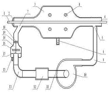
[0016] The embodiments of the present invention are one of many preferred solutions. In order to make the purposes, technical solutions and advantages of the embodiments of the present invention clearer, the technical solutions in the embodiments of the present invention will be clearly and completely described below with reference to the accompanying drawings. Obviously, The described embodiment is a part of the embodiments of the present invention, but not all of the embodiments do not limit the copper-coated steel wire hot air circulation drying system. Tangential spiral air inlet 5, cyclone air drying cylinder 3, inclined three-way air outlet 7, return air bend 13, return air duct 11, and air inlet of automatic temperature-controlled hot air blower 10 are sequentially formed in series.

[0017] The cyclone air drying cylinder 3 has three sections of small-diameter pipes with a wire inlet at the front, a steam trap 6 at the lower part of the large-diameter pipe in the middle...


PUM


Abstract

The invention discloses a hot air circulation drying system for copper-plated steel wires. After the circulating drying air is heated and pressurized by an automatic temperature-control hot air blower, it is introduced into the inner cavity of a cyclone airflow drying cylinder through a hot air channel and a tangential spiral air inlet. The outlet of the oblique tee at the inlet end of the line is discharged, and the saturated steam evaporated by the water film on the surface of the line is taken away. After the water mist is absorbed by the rotary filter device, the drying pipe absorbs the water again, and then sent to the automatic temperature control system through the return air duct. The air inlet of the hot air blower is circulated to heat and pressurize. There is an insulation layer on the outside of the cyclone airflow drying cylinder, and a turbulent drying section in the inner cavity; there is a steam trap in the low-pressure evaporation and separation section, and moisture evaporation windows are distributed on the wall of the cylinder; the water film drive-off section on the surface of the metal wire. The rotary adsorption net device drives the fan blades to drive the filter disc on the rotary shaft to rotate at high speed. After the water mist is absorbed by the filter disc, it is centrifugally thrown to the variable diameter tube shell and discharged by the drain valve; the rotary filter disc is made of fiber Wire or metal, plastic monofilament woven multi-layer composition. The drying tube is a heat-resistant, high air resistance tube.

Description

technical field [0001] The invention relates to the technical field of drying, in particular to a copper-coated steel wire drying system. Background technique [0002] At present, the post-finishing of continuous copper electroplating of steel wires requires closed treatment, water washing and drying processes; steel wire pickling lines, galvanized wires, enameled wires and color-coated wires produced by steel wire manufacturers generally also need to be dried with hot air dryers, while other The drying method for metal wire drying has some shortcomings. Generally, a fan is used for drying to extract air at room temperature of about 20 °C into the air heater and heat it to 150 to 180 °C. The heated air transfers heat to the metal wire while spraying on the surface of the wet metal wire, and at the same time takes away the moisture on the surface of the metal wire. water vapor, thereby drying the wet metal wire. After the hot air is dried on the surface of the metal wire, a...

Claims


Application Information

Patent Timeline
Patent Type & Authority Patents(China)
IPC IPC(8): F26B21/04F26B25/00B05D3/02
Inventor 徐国栋刘玉岩乔娇姚丹丹邵德志柴源郑文彬
Owner 长春航天安可工业有限公司
Learn More