Non-intrusive ultrasonic detection method of mud flow rate in deepwater drilling riser

A deep-sea drilling, non-invasive technology, applied in the direction of fluid velocity measurement, velocity/acceleration/shock measurement, measuring devices, etc., can solve the problems of short gas intrusion treatment time, high cost, large ultrasonic attenuation, etc., and achieve detection speed Fast, high accuracy, timely response effect

Active Publication Date: 2015-12-09
CHINA NAT OFFSHORE OIL CORP +1
View PDF3 Cites 4 Cited by
  • Summary
  • Abstract
  • Description
  • Claims
  • Application Information

AI Technical Summary

Problems solved by technology

The advantage of the interventional method is that the measurement is more accurate, but the pipeline structure needs to be modified during installation, which may have a great impact on the pipeline structure and performance
However, the riser used in the drilling industry itself has strict technical requirements, so the intrusive flow detection method is not suitable for the situation below sea level
On the other hand, the ultrasonic flowmeter is the most widely used in the non-invasive method, but the conventional ultrasonic flowmeter method cannot be applied due to the large attenuation of the ultrasonic wave by the mud
Other non-invasive methods, such as pressure difference method, radiation method, etc., are aimed at the deep sea drilling environ

Method used


Image

  • Non-intrusive ultrasonic detection method of mud flow rate in deepwater drilling riser
  • Non-intrusive ultrasonic detection method of mud flow rate in deepwater drilling riser
  • Non-intrusive ultrasonic detection method of mud flow rate in deepwater drilling riser

Examples


Embodiment Construction

[0039] The present invention will be described in detail below in conjunction with the accompanying drawings and embodiments.

[0040] The invention provides a non-invasive ultrasonic detection method for mud flow velocity in a deep-sea drilling riser, comprising the following steps:

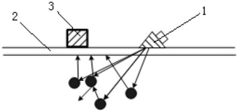
[0041] 1) if figure 1 As shown, the emission sensor 1 is attached to the pipe wall of the riser 2 at an angle of π / 18-4π / 9. The transmitting sensor 1 transmits ultrasonic waves with a frequency of 40KHz-200KHz in a direction consistent with or opposite to the flow velocity of the mud in the riser 2 . The receiving sensor 3 is installed perpendicular to the direction of the pipe wall of the riser 2 at the point with the largest amplitude on the path of the ultrasonic propagation direction.

[0042] 2) Perform corresponding filtering, amplification and other signal processing on the collected actual working signal of the transmitting sensor 1 to obtain the actual working signal frequency f of th...


PUM


Abstract

The invention relates to a non-intrusive ultrasonic detection method of mud flow rate in a deepwater drilling riser. The method comprises the steps that 1) an emission sensor is close to the wall of a riser, and a receiving sensor is arranged on an ultrasonic wave propagation path in the direction vertical to the wall of the riser; 2) the actual work signal frequency and the echo signal intermediate frequency shift information of the emission sensor are acquired; 3) difference frequency signals are acquired, and the difference frequency signal frequency is calculated; 4) the difference frequency signal of the theoretical difference frequency signal frequency maximum is rejected; 5) time frequency conversion is carried out on the difference frequency signals to acquire the frequency domain information of amplitude-frequency or power-frequency; 6) difference frequency signals with amplitude value less than 2% of the maximum amplitude value or with power value less than 2% of the maximum power value are removed, and weighted integral is carried out on remaining frequency to acquire a frequency difference result; 7) a curve of the relationship between the mud flow rate and the frequency difference result is acquired; and 8) according to ultrasonic, the mud flow rate is calculated through the frequency difference result of the riser. The non-intrusive ultrasonic detection method provided by the invention can be widely used for the detection of the mud flow rate in the deepwater drilling riser.

Description

technical field [0001] The invention relates to a mud flow velocity detection method, in particular to a non-intervention ultrasonic detection method of the mud flow velocity in a deep sea drilling riser. Background technique [0002] As an important means to prevent blowout accidents, early overflow monitoring plays an extremely important role in the process of oil drilling. The traditional early overflow detection methods mainly include mud pool incremental method, outlet flow meter method and acoustic wave method. Among them, the actual principles of the mud pool incremental method and the outlet flowmeter method are the same, and both are judged by the incremental change of the outlet mud. Due to the pressure imbalance between the formation fluid and the drilling fluid, the formation fluid containing a large amount of natural gas invades the drilling fluid, and rapidly expands and upwells to form an overflow phenomenon. If it cannot be controlled in time, it may cause w...

Claims


Application Information

Patent Timeline
IPC IPC(8): G01P5/24
Inventor 何玉发赵辉蒋世全周建良李迅科胡伟杰周权
Owner CHINA NAT OFFSHORE OIL CORP
Why Eureka
Try Eureka