Color optical filter insensitive to incident angle and preparation method for the same
An incident angle and filter technology, applied in optics, optical components, instruments, etc., to achieve the effect of cost reduction, low cost and simple preparation
- Summary
- Abstract
- Description
- Claims
- Application Information
AI Technical Summary
Problems solved by technology
Method used
Image
Examples
Embodiment 1~5
[0038] The metal film material is Ag; the dielectric film material is silicon-rich silicon oxide (SiOx)
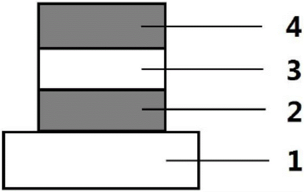
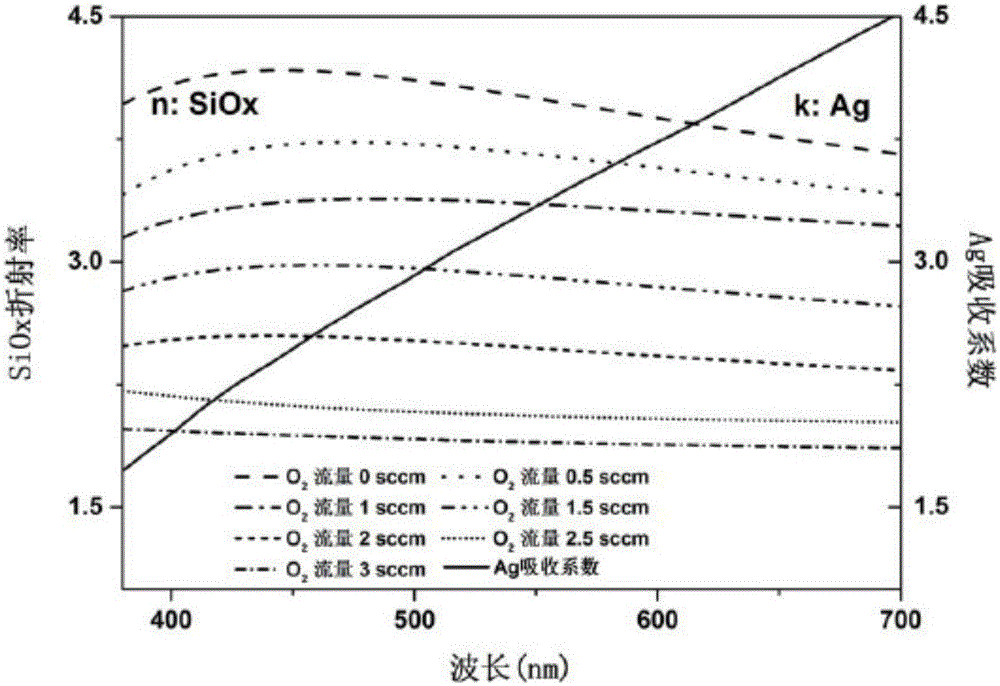
[0039] Such as figure 1 As shown, a color filter that is not sensitive to the incident angle is composed of a substrate 1, and a metal film 2 (Ag), a dielectric film 3 (silicon-rich silicon oxide (SiOx)) and a metal film 4 ( Ag) composition, the dielectric constant of the dielectric film and the metal film material in the working band are opposite in positive and negative, and the absolute value is the same, based on the characteristics of adjustable refractive index of SiOx, the central wavelength of the color filter that is not sensitive to the incident angle Can cover the entire visible light band.
[0040] A method for preparing a color filter that is not sensitive to an incident angle, comprising the following steps,
[0041] 1) For the color filter expected to have a specific central wavelength, the corresponding thickness of the dielectric film SiOx, the thickness...
Embodiment
[0046] Embodiment parameter is as follows table 1:
[0047] Table 1
[0048]
[0049] Angle-insensitive filters with 5 different resonance wavelengths can be produced according to the parameters shown in the table above.
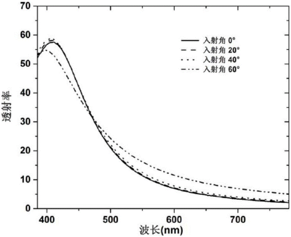
[0050] Carry out P polarized light transmission experiment to the optical filter that embodiment 1-5 prepares respectively, the P polarized light transmission spectrogram that obtains sees Figure 3-7 ,in image 3 It is the P polarized light transmission spectrum figure corresponding to embodiment 1, Figure 4 It is the P polarized light transmission spectrum figure corresponding to embodiment 2, Figure 5 It is the P polarized light transmission spectrum figure corresponding to embodiment 3, Figure 6 It is the P polarized light transmission spectrum figure corresponding to embodiment 4, Figure 7 It is the P polarized light transmission spectrum figure corresponding to embodiment 5;
[0051] Carry out S polarized light transmission experiment to t...
Embodiment 6-11
[0054] see Figure 13 , choose silicon-rich silicon nitride SiNy as the dielectric thin layer material; Ag metal thin film material;
[0055] By using a method similar to that of Examples 1-5 and carrying out Examples 6-11 according to the parameters shown in Table 2, another 6 angle-insensitive filters with different resonance wavelengths can be produced.
[0056] Table 2
[0057]
[0058] Carry out P polarized light transmission experiment to the optical filter that embodiment 6-11 prepares respectively, the obtained P polarized light transmission spectrogram sees Figure 14-19 ,in Figure 14 It is the P polarized light transmission spectrum figure corresponding to embodiment 6, Figure 15 It is the P polarized light transmission spectrum figure corresponding to embodiment 7, Figure 16 It is the P polarized light transmission spectrum figure corresponding to embodiment 8, Figure 17 It is the P polarized light transmission spectrum figure corresponding to embodiment...
PUM
| Property | Measurement | Unit |
|---|---|---|
| thickness | aaaaa | aaaaa |
| thickness | aaaaa | aaaaa |
| refractive index | aaaaa | aaaaa |
Abstract
Description
Claims
Application Information
 - R&D
- Intellectual Property
- Life Sciences
- Materials
- Tech Scout
- Unparalleled Data Quality
- Higher Quality Content
- 60% Fewer Hallucinations
Browse by: Latest US Patents, China's latest patents, Technical Efficacy Thesaurus, Application Domain, Technology Topic, Popular Technical Reports.
© 2025 PatSnap. All rights reserved.Legal|Privacy policy|Modern Slavery Act Transparency Statement|Sitemap|About US| Contact US: help@patsnap.com


