Electric vehicle charging system

A charging system, electric vehicle technology, applied in electric vehicle charging technology, electric vehicles, charging stations, etc., can solve the problems of large input differential mode and common mode interference, system complexity, circuit complexity increase, etc., and achieve high power factor , No high frequency switching loss, the effect of improving reliability

Inactive Publication Date: 2015-12-09
XIAN TGOOD INTELLIGENT CHARGING TECH CO LTD
View PDF2 Cites 15 Cited by
  • Summary
  • Abstract
  • Description
  • Claims
  • Application Information

AI Technical Summary

Problems solved by technology

Objectively, the circuit complexity increases. Since the PFC circuit adopts high-frequency PWM control, it has large input differential mode and common mode interference on the input side. At the same time, be

Method used


Image

  • Electric vehicle charging system
  • Electric vehicle charging system
  • Electric vehicle charging system

Examples


Embodiment Construction

[0026] The present invention is described in further detail below in conjunction with accompanying drawing:

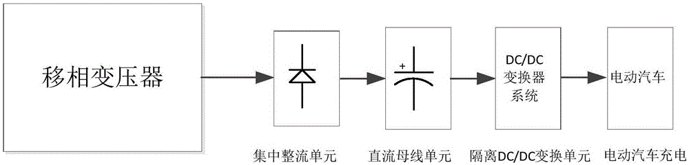
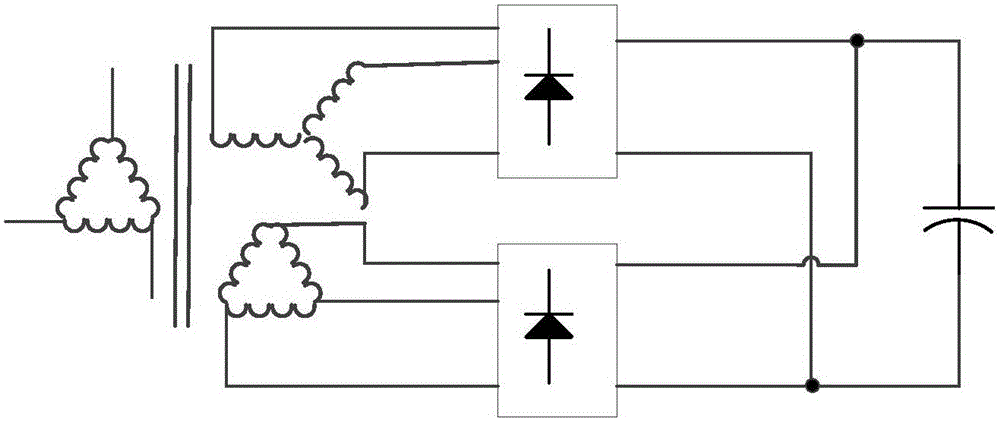
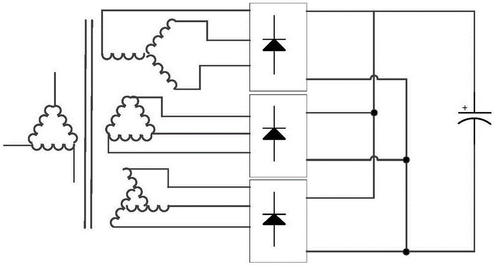
[0027] Such as figure 1 As shown, an electric vehicle charging system includes a phase-shifting rectifier transformer connected to an external power grid. The rear stage of the phase-shifting rectifier transformer is connected to a centralized rectification unit to form a rectification circuit. The phase-shifting rectifier transformer is multi-pulse rectification, which can reduce the input THDI of the system, that is, the distortion rate of the input current, and the secondary side of the phase-shifting rectifier transformer has two or two groups The above secondary windings, these secondary windings are respectively connected to the centralized rectification unit; for example figure 2 , image 3 , Figure 4 , Figure 5 As shown in , the rectification element in the centralized rectification unit is an SCR thyristor or a diode, such as Figure 5 , Figure 6 As ...


PUM


Abstract

The invention belongs to the vehicle charging technology field and discloses an electric vehicle charging system. The system comprises a phase-shifting rectifier transformer connected to an external power grid. A backward stage of the phase-shifting rectifier transformer is connected to a concentration rectifier unit. A backward stage of the concentration rectifier unit is connected to a direct current bus unit and a backward stage of the direct current bus unit is connected to a DC/DC conversion circuit. In the invention, a concentration-type multiple pulse wave rectifier is used to replace multiple groups of modular parallel PWM-type high frequency PWM rectification circuits. An input terminal of the circuit is the phase-shifting rectifier transformer. Through transformer rectification, a high power factor and a low current harmonic wave are realized. Simultaneously, a concentration-type power factor rectification circuit shares a transformer whose an input high voltage is converted into a low voltage; the transformer is reconstructed into the phase-shifting rectifier transformer so that cost is greatly reduced. A rectifying element works in a power frequency work state, there is no high frequency switch losses and no common mode interferences caused by a high speed switch, efficiency is increased, reliability is improved and cost is reduced.

Description

technical field [0001] The invention belongs to the technical field of automobile charging, in particular to an automobile charging system. Background technique [0002] In the current design of the centralized high-power electric vehicle charging system, the generally adopted architecture is a 10KV high-voltage input, which is stepped down to a 380V three-phase AC voltage system through a high-voltage isolation transformer. Then the AC power is connected to the AC / DC charging module through the power distribution system. The AC / DC charging module generally has a two-stage structure, PFC rectification and isolated DC / DC converter structure. [0003] Its characteristic is that the high-voltage transformer is an ordinary star-to-delta transformer, and the transformer is only used as a high-voltage and low-voltage isolation function. The power electronics conversion equipment, namely the charging module, is connected to the rear stage of the transformer. The charging module c...

Claims


Application Information

Patent Timeline
IPC IPC(8): H02J7/02
CPCB60L2210/10B60L2210/30B60L53/11Y02T10/70Y02T10/7072Y02T10/72Y02T90/14
Inventor 袁庆民
Owner XIAN TGOOD INTELLIGENT CHARGING TECH CO LTD
Why Eureka
Try Eureka