High-pressure high-speed axial piston pump piston pair four-axis force testing device

A technology of axial piston pump and testing device, which is applied in the field of hydraulic components, can solve the problems of low maximum speed and pressure, interference of support installation force, high cost, etc., and achieve high lubricating performance, reliable overall structure, and simple overall structure Effect

Active Publication Date: 2015-12-23
ZHEJIANG UNIV
View PDF8 Cites 11 Cited by
  • Summary
  • Abstract
  • Description
  • Claims
  • Application Information

AI Technical Summary

Problems solved by technology

RWTH Aachen University in Germany, Purdue University in the United States, Tokyo Institute of Technology in Japan and Harbin Institute of Technology in China have all designed such test devices based on this idea. Among them, the test devices developed by RWTH Aachen University and Tokyo Institute of Technology can only test the plunger pair. The friction force in the axial direction, although the test device developed by Purdue University can realize the force measurement in the three directions of the plunger pair x, y and z axes by using wireless telemetry technology, but the cost is expensive and the cost is extremely high. Harbin Industrial Co., Ltd. The test device developed by the university installs the patch-type strain gauge sensor at the contact position of the plunger pair to measure the stress, and then calculates and analyzes the friction force in the z-axis direction of the plunger pair and the lateral force in the x and y-axis directions. Force, obtained through indirect measurement, this method is also easily disturbed by the installation force of the support
The maximum allowable speed and pressure of these existing test devices are lower than the rated value of the pump

Method used


Image

  • High-pressure high-speed axial piston pump piston pair four-axis force testing device
  • High-pressure high-speed axial piston pump piston pair four-axis force testing device
  • High-pressure high-speed axial piston pump piston pair four-axis force testing device

Examples


Embodiment Construction

[0021] The present invention will be further described in detail below in conjunction with the accompanying drawings.

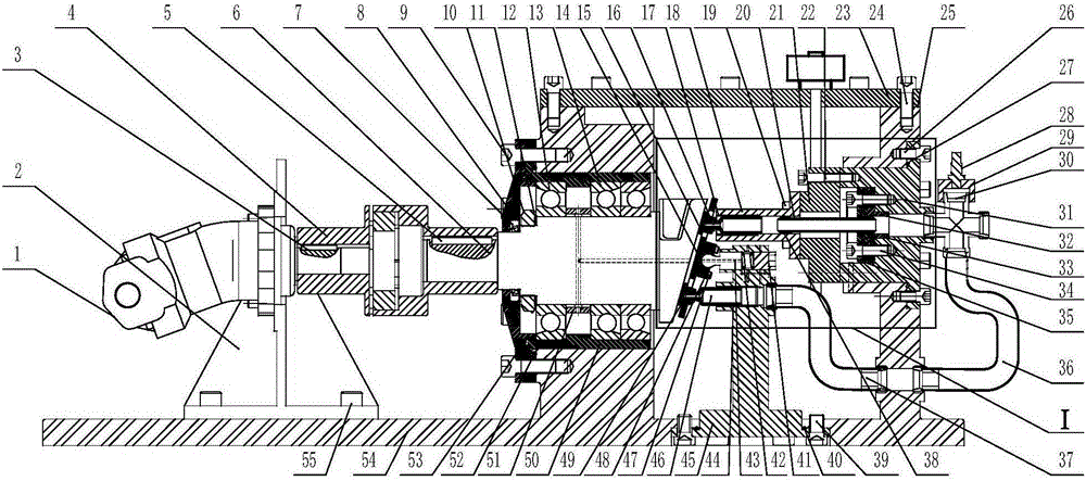
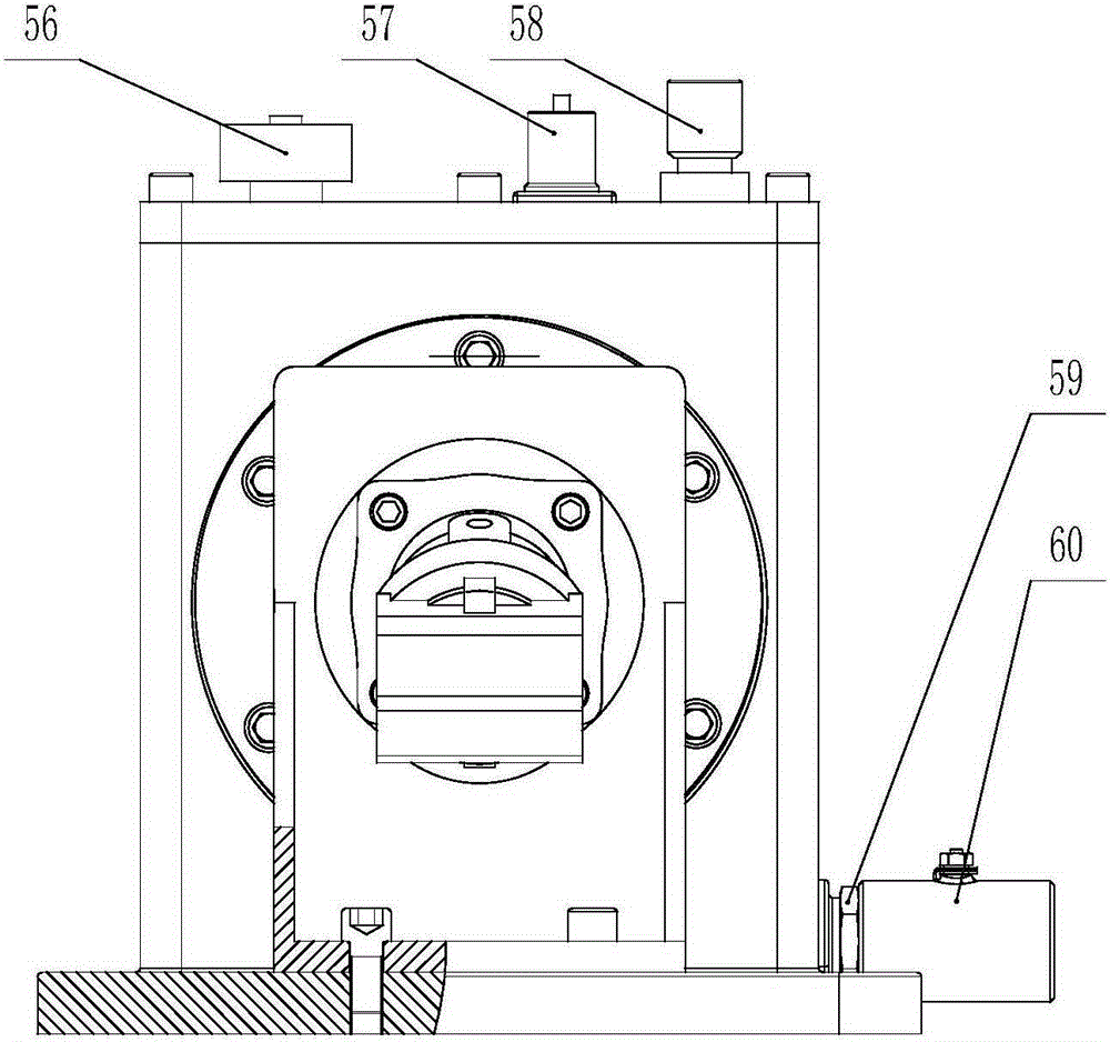
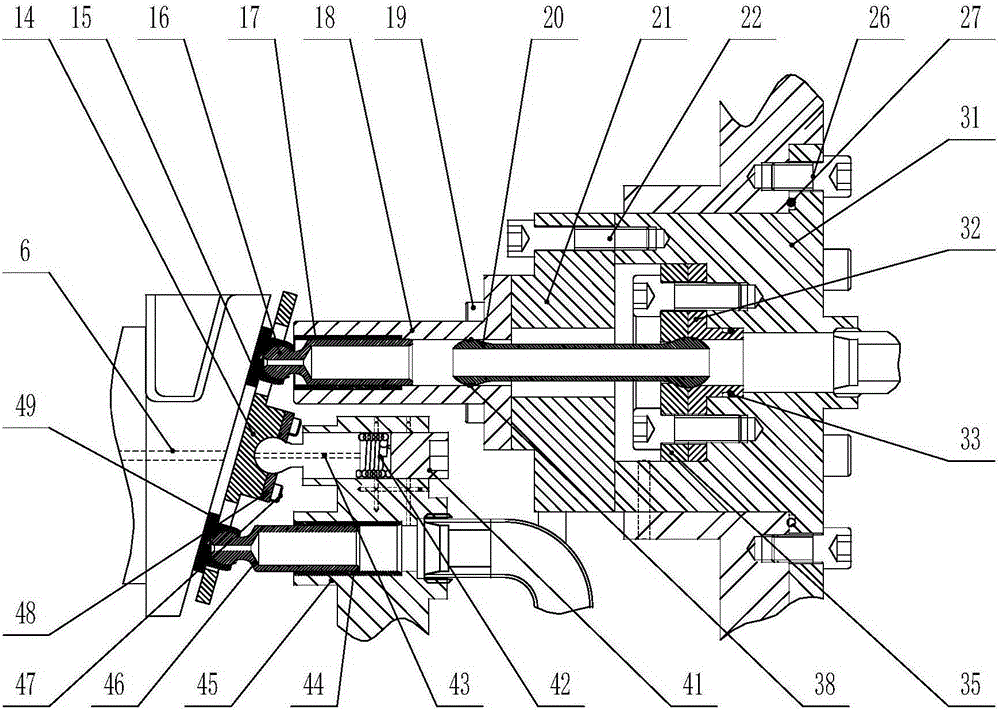
[0022] like figure 1 As shown, a high-pressure high-speed axial plunger pump plunger pair four-axis force test device includes: a transmission part, a support part, a plunger pair part to be tested, an auxiliary plunger pair part, a casing upper cover 23, an upper Cover screw 24, sealing gasket 25, pressure sensor 28, pressure sensor base 29, four-way joint 30, housing 54, liquid level switch 56, temperature sensor 57, air filter 58, straight joint 59 and oil drain stop valve 60; wherein, the transmission part is installed on the housing 54; the plunger chamber of the measured plunger sub-part and the plunger chamber of the auxiliary plunger sub-part are all connected to the four-way joint 30; the pressure sensor 28 is connected to the pressure sensor base 29 The four-way joint 30 is connected; a temperature sensor 57, a liquid level switch 56 and an air fil...


PUM


Abstract

The invention discloses a high-pressure high-speed axial piston pump piston pair four-axis force testing device which is mainly composed of a swash plate shaft, a bearing assembly, a tested piston pair, an auxiliary piston pair, a four-axis force sensor, an oil lead piston, a piston base, a piston shoe press plate, a preloaded piston, a compression spring, a spring seat and the like. The ingenious lubrication structure of the ball head and hinge joint of the preloaded piston with adjustable pretension and the bearing assembly, the swash plate shaft in a dynamic balance balancing structure, the tested piston pair, the auxiliary piston pair, the oil lead piston and the four-axis force sensor with a center through hole structure are designed. The tested piston pair and the auxiliary piston pair are symmetrically arranged. The ball head structure of different sizes on both ends and the ball hinge pair of the oil lead piston are connected. Interference factors on the tested piston pair are eliminated. Three-dimensional direction action force and axial torque of a high-pressure high-speed piston pair are measured. The device has the advantages of simple and reliable overall structure, easy part replacing and low machining and detection cost.

Description

technical field [0001] The invention relates to the technical field of hydraulic components, in particular to a four-axis force testing device for a plunger pair of a high-pressure high-speed axial plunger pump. Background technique [0002] Axial piston pump is one of the most important power components in the field of fluid transmission and control. It has been widely and deeply used in all walks of life. With the continuous development of industrial technology, axial piston pumps The urgent demand for higher working speed, higher working pressure and wider high-efficiency zone is put forward. The plunger pair is the core friction pair for the axial piston pump to realize the oil suction and discharge function. The frictional lubrication performance and load-carrying performance of the plunger pair have a decisive impact on the high-speed, high-pressure, and high-efficiency performance of the axial piston pump. The friction and lubrication performance of the plunger pair ...

Claims


Application Information

Patent Timeline
Patent Type & Authority Applications(China)
IPC IPC(8): G01L5/00
Inventor 徐兵胡敏夏士奇张军辉岳艺明
Owner ZHEJIANG UNIV
Why Eureka
Try Eureka