
Urea mixer of SCR system

A mixer and urea technology, applied in the direction of machine/engine, muffler, engine components, etc., can solve the problems of increasing the back pressure of the exhaust system, blocking the exhaust pipe, and taking away the exhaust gas flow, so as to enhance the agitation, reduce the Crystallization and avoidance of ammonia leakage

Active Publication Date: 2015-12-30
NANJING IKAKAT EMISSIONS TECH CO LTD
View PDF6 Cites 15 Cited by
  • Summary
  • Abstract
  • Description
  • Claims
  • Application Information

AI Technical Summary

Problems solved by technology

Moreover, at the urea injection area on the exhaust pipe, the urea aqueous solution sprayed on the exhaust pipe cannot be completely taken away by the exhaust gas flow, and crystallization or deposits are likely to appear there, resulting in blockage of the exhaust pipe and increased exhaust system back pressure

Method used


Image

  • Urea mixer of SCR system
  • Urea mixer of SCR system
  • Urea mixer of SCR system

Examples


Embodiment 1

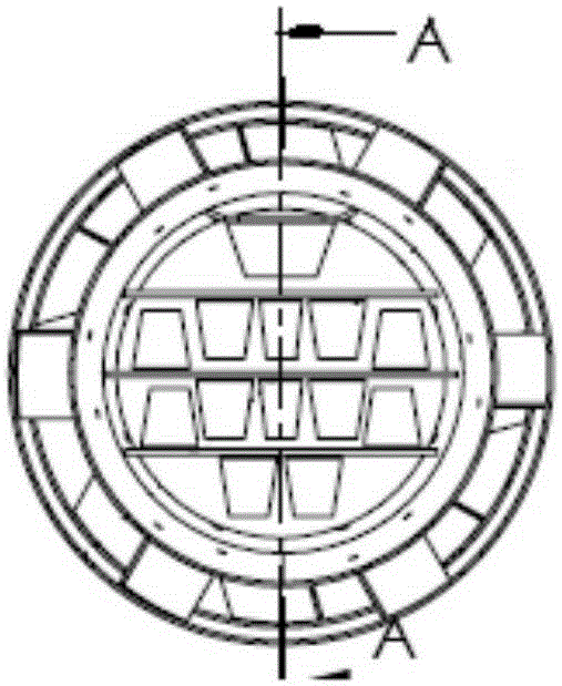
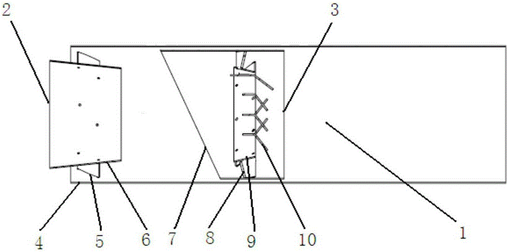
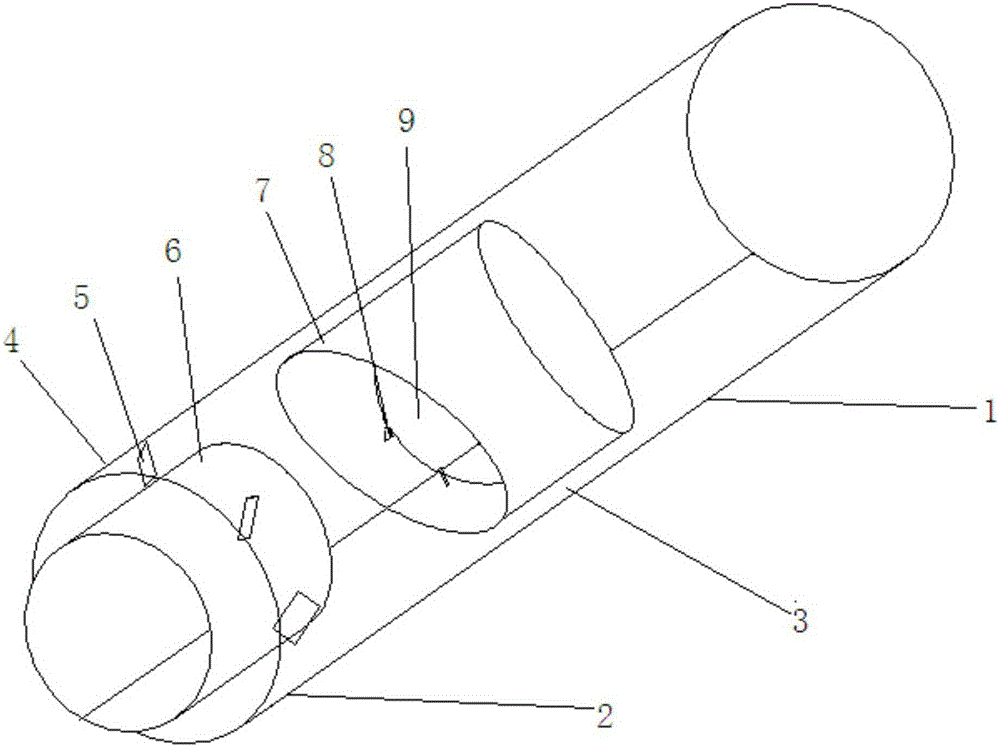
[0032] refer to figure 1 , figure 2 and image 3 , the figure is a specific embodiment of the SCR system urea mixer of the present invention.

[0033] The SCR urea mixer 1 shown in the figure comprises a mixer front part 2 and a mixer rear part 3 .

[0034] Wherein, the front portion 2 of the mixer comprises an annular housing 4, rotating blades 5 and a guide ring 6, the guide ring 6 is placed in the center of the annular housing 4, and the guide ring 6 and the annular housing 4 A number of rotating blades 5 are evenly arranged therebetween, and the two sides of the rotating blades 5 are fixedly connected to the annular casing 4 and the guide ring 6 respectively. The rotating blades 5 form a certain angle with the central axis of the annular housing 4 and are arranged around the central axis in the same rotation direction. The guide ring 6 is trumpet-shaped, and the diameter of the air inlet end is larger than the diameter of the air outlet end.

[0035] The rear part of t...


PUM


Abstract

The invention provides a urea mixer of an SCR system. The mixer is capable of fully changing the flow direction of urea to make urea evenly mixed with waste gas and reducing blockages such as crystals and sediment on the urea jet breadth to avoid ammonia leakage. A blade device is installed behind a urea nozzle, the number of blades is increased, and airflow is changed by the blades to form intense perturbance so as to improve the mixing effect of a urea water solution and waste gas spray. Under the stirring action of the multiple blades, the flowing direction of the urea water solution is changed, and the urea water solution is fully mixed with the waste gas. Meanwhile, the structure of a flow guide ring in the mixer is changed, so that urea on the urea jet breadth falls off from the flow guide ring under driving of the airflow, the crystals and the sediment are reduced, and ammonia leakage is avoided.

Description

technical field [0001] The invention belongs to the field of emission pollution control of internal combustion engines, in particular to a urea mixer for an SCR system. Background technique [0002] Selective Catalytic Reduction (SCR) is a technology that targets NO in diesel vehicle exhaust emissions. x A treatment process, that is, under the action of a catalyst, the reducing agent ammonia or urea is injected to remove the NO in the tail gas x reduced to N 2 and H 2 O. Diesel engine urea SCR technology has been used in Europe for several years, and it is the mainstream technology route in Europe to meet Euro IV / V emission requirements. In the United States, in order to meet the more stringent EPA2010 emission regulations, most engine manufacturers have begun to use SCR technology. In my country, urea SCR technology is considered to be the most feasible NO solution for heavy-duty diesel engines because of its good sulfur resistance. X Emission Control Aftertreatment T...

Claims


Application Information

Patent Timeline
Patent Type & Authority Applications(China)
IPC IPC(8): F01N3/28
Inventor 胡广周艳波米索·亨瑞克·海那艾侯董华平汪旻浩
Owner NANJING IKAKAT EMISSIONS TECH CO LTD
Learn More