Transmitting digital beam forming method based on digital delay and phase compensation

A digital delay and digital beam technology, applied in radio wave measurement systems, instruments, etc., can solve the problems of broadband signal side frequency phase error, can not meet the requirements of beam control phase accuracy, and do not consider the method of multi-phase design.

Active Publication Date: 2015-12-30
HOHAI UNIV
View PDF4 Cites 14 Cited by
  • Summary
  • Abstract
  • Description
  • Claims
  • Application Information

AI Technical Summary

Problems solved by technology

[0008] a. The delay resolution (minimum delay amount) cannot meet the phase accuracy requirements of beam control, and it is necessary to perform delay and phase control at the same time;
[0009] b. Limited delay resolution, resulting in wideband signal side frequency phase error, deteriorating the sidelobe performance of wideband beams
[0010] In recent years, the research on continuously adjustable digital delay lines in the world has made great progress, and many theories and design methods have been proposed, which are mainly used in communication modems, speech synthesis and other fields. The signal sampling rate is relatively low, and many phase design method

Method used


Image

  • Transmitting digital beam forming method based on digital delay and phase compensation
  • Transmitting digital beam forming method based on digital delay and phase compensation
  • Transmitting digital beam forming method based on digital delay and phase compensation

Examples


Embodiment Construction

[0077] Below in conjunction with accompanying drawing, technical scheme of the present invention is described in further detail:

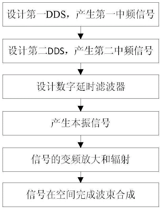
[0078] The present invention is based on digital delay and phase compensation transmit digital beamforming method, its implementation steps are as follows figure 1 shown.

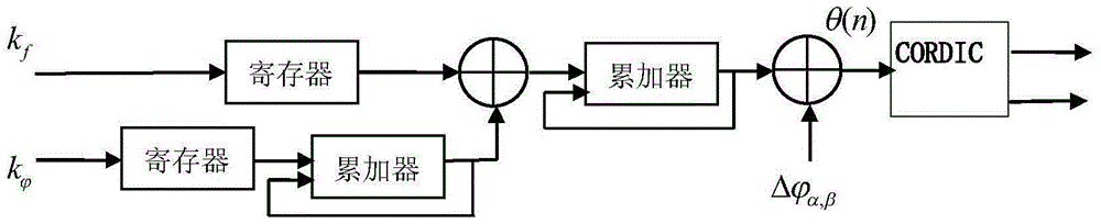
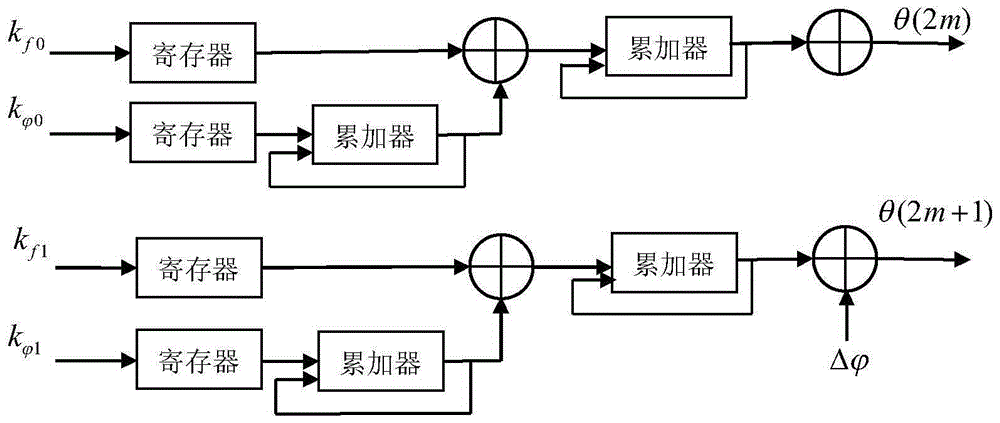
[0079] Step 1, design the first DDS, produce the first intermediate frequency signal, the first intermediate frequency signal is single carrier frequency signal or narrowband linear frequency modulation (LFM) signal, as figure 2 shown, including:

[0080] (1a) According to the parameters of the digital array radar system, use double accumulators in the FPGA to generate the phase of the first intermediate frequency signal, and calculate the compensation frequency and compensation phase.

[0081] The phase of the first intermediate frequency signal is:

[0082]

[0083] In the formula, n represents the number of sampling points of the first intermediate frequency signal; π ...


PUM


Abstract

The invention discloses a digital transmitting beam forming method based on digital delay and phase compensation. According to the method, a first DDS is designed by means of two accumulators and the CORDIC algorithm in an FPGA, and a simulative first intermediate-frequency signal is obtained; a second DDS is designed by means of the multiphase processing technique in an FPGA, a digital baseband signal of a second intermediate-frequency signal is obtained by means of two accumulators and the CORDIC algorithm, and a simulative second intermediate-frequency signal is obtained through interpolated filter digital frequency conversion; a frictional delay filter and an integral delay filter are designed, and a digital delay filter is realized in four phases; a first local oscillation signal and a second local oscillation signal are generated by means of output reference clock signals and frequency agility local oscillation signals, and a radio-frequency signal is generated through frequency mixing filtration; the radio-frequency signal is transmitted through an antenna array after being amplified, and beam forming is achieved in the space. According to the method, a narrow-band signal and a broad-band signal are generated by means of multiple DDS combinations, and narrow-band signal and broad-band signal transmitting beam forming is achieved by means of phase control and continuously variable digital delay.

Description

technical field [0001] The invention relates to a transmitting digital beamforming method based on digital delay and phase compensation, and belongs to the technical field of array signal processing. Background technique [0002] Phased array radar can complete various tasks such as target search, tracking, and guidance, so it is widely used in fields such as multi-target ballistic measurement, air defense warning, and multi-target tracking and guided weapon systems. Requirements such as large airspace, multiple targets, and anti-jamming urge radar to develop in a digital direction. Digital array radar is the direction of future phased array radar technology development. The requirements for imaging and identifying targets have prompted radars to use wideband and high-resolution signal waveforms. Existing digital arrays for narrowband signals are controlled by DDS-based digital phase shifting methods for digital beamforming, but digital arrays for transmitting broadband sig...

Claims


Application Information

Patent Timeline
Patent Type & Authority Applications(China)
IPC IPC(8): G01S7/02
CPCG01S7/02
Inventor 蒋德富付伟苏宇钱荣沈明威魏爽
Owner HOHAI UNIV
Why Eureka
Try Eureka