Walking pneumatic wall-climbing robot
A wall-climbing robot and walking technology, applied in the field of wall-climbing robots, can solve the problems of poor adsorption, small motion torque, weak load-bearing capacity, etc., and achieve the effects of reliable adsorption performance, simple direction control, and strong load-bearing capacity.
- Summary
- Abstract
- Description
- Claims
- Application Information
AI Technical Summary
Problems solved by technology
Method used
Image
Examples
Embodiment 1
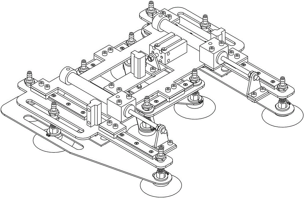
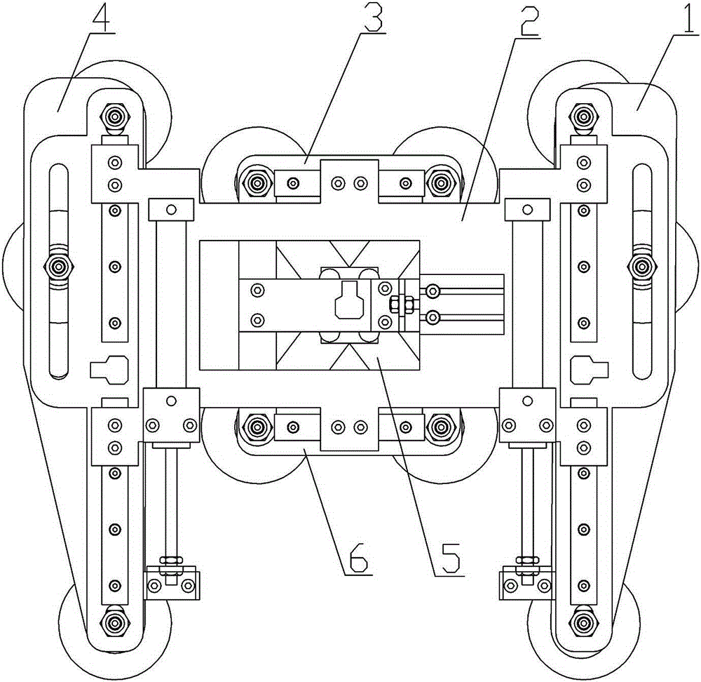
[0062] Embodiment 1, the present invention includes a mechanical structure, a pneumatic system and a vacuum adsorption system. An air compressor is used to provide an air source for the pneumatic system, thereby avoiding motor rotation noise. The power source is provided by an air compressor, and air pressure is used to drive a pair of long legs and short legs that move relative to the frame 2, that is, the right long leg 1, the left long leg 4, the front short leg 3, and the rear short leg 6. Simultaneously control the vacuum suction cups 12 on the long and short limbs to alternately absorb and climb the wall; the mechanical device mainly includes a frame 2, a pair of long limbs, namely the right long limb 1, a left long limb 4, and a pair of short limbs, namely the front short Legs 3 and rear short legs 6; right long leg 1 and left long leg 4 adopt a left-right symmetrical layout, which can move up and down parallel to the wall, and can move up and down vertically within a ce...
Embodiment 2
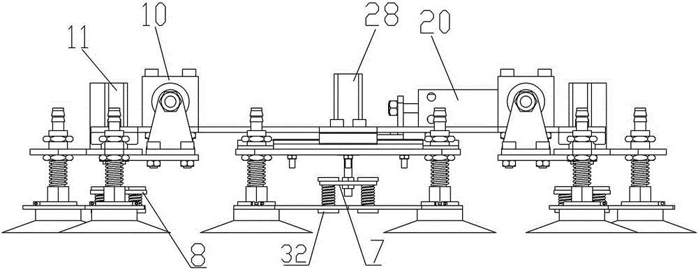
[0063] Embodiment 2, the right long limb 1, the left long limb 4, the front short limb 3, and the rear short limb 6 of the present invention have compressibility, and the right long limb 1 and the left long limb 4 can The vertical frame 2 moves up and down within the height range, and it includes four parts: the long limb connecting bracket 14, the long limb lifting bracket 15, the long limb slider 13, the long limb guide rail 16, and the long limb buffer device 8, and the long limb connecting bracket 14 The suction cup 12 is fixed, and the long-limb walking cylinder 10 is installed on the frame 2 to drive the right long-limb leg 1 and the left long-limb leg 4 to move up and down parallel to the wall, and is fixed by a bolt 25 connection; wherein the long-limb lifting cylinder 11 is installed on the long-leg connecting bracket 14 drives the long-limb buffer device 8 to drive the long-limb lifting bracket 15 to move up and down the suction cup 12 fixedly connected to realize the...
Embodiment 3
[0064] Embodiment 3, the buffer device 7 for short limbs and the buffer device 8 for long limbs include springs and guide rods. Take the short limb buffer device 7 as an example, the base 32 is installed on the lower surface of the short limb lifting bracket 5, one end of the fixed spring 29, the guide rod 30 is installed on the cylinder connecting bracket 31, the spring 29 is sleeved on the guide rod 30, and the spring 29 is another One end links to each other with short limb lifting support 5. The cylinder connection bracket 31 is connected with the short limb lifting bracket 5 by a spring 29 and has a buffering effect. refer to Figure 1 to Figure 8 , all the other are with above-mentioned embodiment 1.
PUM
 Abstract
Description
Claims
Application Information
 - R&D
- Intellectual Property
- Life Sciences
- Materials
- Tech Scout
- Unparalleled Data Quality
- Higher Quality Content
- 60% Fewer Hallucinations
Browse by: Latest US Patents, China's latest patents, Technical Efficacy Thesaurus, Application Domain, Technology Topic, Popular Technical Reports.
© 2025 PatSnap. All rights reserved.Legal|Privacy policy|Modern Slavery Act Transparency Statement|Sitemap|About US| Contact US: help@patsnap.com


