Heat pump water heating system with function of divided-flow reinforced heat recovery

A heat pump hot water, split-flow technology, applied in heat pumps, fluid heaters, refrigeration and liquefaction, etc., can solve the problems of poor adaptability of two-stage heat exchange site, leakage of refrigerant in disassembly and handling, and restrictions on popularization and application, to ensure The effect of water safety, reduced installation difficulty and maintenance rate, and high thermal energy utilization rate

Active Publication Date: 2016-01-06
广州润达环保科技有限公司
View PDF9 Cites 0 Cited by
  • Summary
  • Abstract
  • Description
  • Claims
  • Application Information

AI Technical Summary

Problems solved by technology

This structure makes good use of the two-stage heat exchange method to increase the recovery effect of waste water waste heat, and the auxiliary heating also increases the applicability of the product, but it is precisely the poor adaptability of the two-stage heat exchange on site that restricts its large-scale popularization and application. The reason is that There are two types of pipelines (cold water pipe and refrigerant pipe) built into the waste heat recovery device, which are expensive to manufacture and difficult to install, and easy to cause refrigerant leakage due to disassembly and handling

Method used


Image

  • Heat pump water heating system with function of divided-flow reinforced heat recovery

Examples


Embodiment Construction

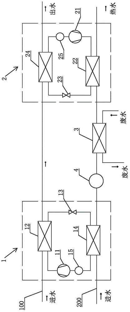
[0012] refer to figure 1 , the heat pump hot water system with split-flow enhanced heat recovery of the present invention includes a first heat pump device 1, a second heat pump device 2, a heating device 3 for heating water flow, a first water inlet flow path 100 and a second water inlet flow path 200 , the first heat pump device 1 includes a first compressor 11, a first condenser 12, a first throttling device 13 and a first evaporator 14 forming a circulation loop, and the second heat pump device 2 includes a circulation loop The second compressor 21, the second condenser 22, the second throttling device 23 and the second evaporator 24, the first water inlet flow path 100 passes through the first condenser 12 and the second evaporator 24, the second water inlet flow path 200 Via the first evaporator 14 , the heating device 3 and the second condenser 22 , the heating device 3 is arranged between the first evaporator 14 and the second condenser 22 . In order to ensure the use...


PUM


Abstract

Disclosed is a heat pump water heating system with a function of divided-flow reinforced heat recovery. The heat pump water heating system with the function of divided-flow reinforced heat recovery comprises a first heat pump device, a second heat pump device, a heating device, a first inlet water flow path and a second inlet water flow path, wherein the heating device is used for heating water flow. The first heat pump device comprises a first compressor, a first condenser, a first throttling device and a first evaporator, wherein the first compressor, the first condenser, the first throttling device and the first evaporator are combined to form a circulation circuit. The second heat pump device comprises a second compressor, a second condenser, a second throttling device and a second evaporator, wherein the second compressor, the second condenser, the second throttling device and the second evaporator are combined to form a circulation loop. The first inlet water flow path passes through the first condenser and the second evaporator, the second inlet water flow path passes through the first evaporator, the heating device and the second condenser, the heating device is arranged between the first evaporator and the second condenser, and an ultraviolet disinfection device is arranged on the second inlet water flow path and arranged between the first evaporator and the second condenser. By the adoption of the structure, the heat absorption effect of the second inlet water flow path is greatly enhanced, refrigerant cannot enter the heating device, the structure is simple, the production cost is low, and the installation difficulty and the maintenance rate are greatly reduced.

Description

technical field [0001] The invention relates to a hot water system, in particular to a heat pump hot water system of split flow enhanced heat recovery. Background technique [0002] When people bathe with hot water in the bathroom, the waste water produced has a high temperature and a large amount of heat energy. In order to make full use of this part of the heat energy, people have proposed a heat pump water heater with two-stage shower waste heat recovery. For example, the patent number is "ZL201320753365.2 "The Chinese patent discloses a bathroom waste heat recovery heat pump hot water system. This structure uses two-stage heat exchange, that is, cold water heat exchange and refrigerant heat exchange to absorb the heat in the waste water. The waste water is discharged after cooling down. Heat exchange, to achieve the first stage heat exchange, and then the waste heat of the waste water is further absorbed by the refrigerant, which is used to heat the water flow after the ...

Claims


Application Information

Patent Timeline
Patent Type & Authority Applications(China)
IPC IPC(8): F24H4/02F25B30/06
Inventor 平武臣
Owner 广州润达环保科技有限公司
Why Eureka
Try Eureka