Automatic laser shot device, shot point identification method and automatic shot point correction method

A technology of automatic shooting and identification methods, which is applied in the directions of weapon accessories, gun control systems, target indication systems, etc., to achieve the effect of promoting development, improving fun, and improving the level of actual combat.

Active Publication Date: 2016-01-06
WENZHOU UNIVERSITY
View PDF4 Cites 4 Cited by
  • Summary
  • Abstract
  • Description
  • Claims
  • Application Information

AI Technical Summary

Problems solved by technology

[0004] There is no laser shooting recognition device that can realize automatic aiming, automatic shooting, automatic recognition of

Method used


Image

  • Automatic laser shot device, shot point identification method and automatic shot point correction method
  • Automatic laser shot device, shot point identification method and automatic shot point correction method
  • Automatic laser shot device, shot point identification method and automatic shot point correction method

Examples


Embodiment 1

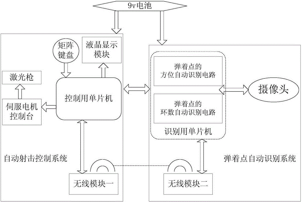
[0055] Embodiment 1, combining figure 1 and figure 2 , a laser automatic shooting device, comprising an automatic shooting control system and an automatic impact point recognition system, the automatic shooting control system comprising:

[0056] Wireless module 1, a matrix keyboard, a single-chip microcomputer connected to the matrix keyboard and controlled by it, a servo motor console connected to and controlled by the single-chip microcomputer, and a laser gun located on the servo motor console;

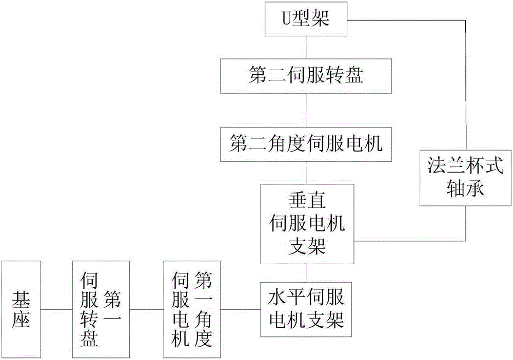
[0057] The servo motor console includes a base, a first angle servo motor, a second angle servo motor, a horizontal servo motor bracket, a vertical servo motor bracket, a U-shaped frame, a first servo turntable, a second servo turntable and a flange cup type Bearings, the first angle servo motor is fixed on the horizontal servo motor bracket, the output shaft of the first angle servo motor is connected with the first servo turntable with interference fit, the first servo turntab...

Embodiment 2

[0063] Embodiment 2: A kind of laser automatic shooting device as described in embodiment 1, automatic shooting control system also includes liquid crystal display module, is used for reporting target, comprises display chest ring target, the ring number of impact point, the bearing of impact point.

Embodiment 3

[0064] Embodiment 3: a kind of laser automatic shooting device as described in embodiment 1, described laser gun comprises the laser modulation tube that connects in sequence, laser emission tube drive circuit, laser emission tube and electromagnetic relay; Automatic shooting control system sends a The control signal is given to the electromagnetic relay, so that the normally open contact of the electromagnetic relay is closed, and the driving circuit of the laser emitting tube is connected, and the laser beam is emitted to the chest ring target.


PUM


Abstract

The invention discloses an automatic laser shot device, a shot point identification method and an automatic shot point correction method. The automatic laser shot device comprises an automatic shot control system and an automatic shot point identification system. The automatic shot control system comprises a first wireless module, a matrix keyboard, a single chip microcomputer, a serve motor control table, a laser gun and the like. The single chip microcomputer is connected with the matrix keyboard and controlled by the matrix keyboard. The serve motor control table is connected with the matrix keyboard and controlled by the matrix keyboard. The laser gun is located on the serve motor control table. Based on the gray value of a pixel, the shot point identification method adopts a non-neighboring-group identification method. According to the automatic shot point correction method, the serve motor control table is adjusted according to the difference value of the coordinates of a shot point and the coordinates of a target, so that shot deviation is corrected. The automatic laser shot device is low in cost and danger, and high in objectivity and precision. The non-neighboring-group identification method based on the gray value of the pixel is adopted to determine the shot point, so that the method is more precise and more efficient, and the precision the method is up to 0.88%.

Description

technical field [0001] The invention relates to the field of laser shooting, in particular to a laser automatic shooting device, a method for recognizing a point of impact, and a method for automatically correcting the point of impact. Background technique [0002] Recognition of the point of impact, the existing technology uses a photodiode array to identify the point of impact. This technology is backward, and the recognition accuracy of the point of impact is not high, and the recognition is not stable enough. PSD (Position Sensitive Detector) is also used as a sensor to identify the impact point. PSD is a continuous analog spot position detection device. Its principle is to use the change of photodiode surface impedance under illumination to detect the position of the spot. This method is susceptible to ambient light, and its accuracy in identifying the point of impact is only 1%. At present, the laser shooting devices on the market cannot realize full automation, and s...

Claims


Application Information

Patent Timeline
IPC IPC(8): F41G5/06F41J5/02
Inventor 王峰
Owner WENZHOU UNIVERSITY
Why Eureka
Try Eureka