Motor and hydraulic pressure combined drive in-situ test device for structure properties of materials

A driving method and technology of tissue properties, applied in the field of in-situ testing devices for material properties The requirements of sample preparation and the effect of shortening the experimental time

Active Publication Date: 2016-01-06
INST OF METAL RESEARCH - CHINESE ACAD OF SCI
View PDF8 Cites 16 Cited by
  • Summary
  • Abstract
  • Description
  • Claims
  • Application Information

AI Technical Summary

Problems solved by technology

The characteristics of X-ray diffraction analysis make it very suitable for the phase analysis of metal materials under different stress conditions. However, for a long time, the samples of X-ray diffraction experiments are in static state. There are the following problems in the process of phase and structure change of metal materials in metal materials: first, several tensile experiments and X-ray diffraction experiments need to be done separately, the number of experiments is large, the number of samples is large, and the experiment cycle is long; The method of obtaining samples by unloading when the tensile test is at different stages cannot ensure that the internal structure and stress state of the material will not change from a certain loading state to an unloading state
This patent has three deficiencies in the in-situ tissue performance experiment of materials; first, the experimental load is limited, and the maximum can only reach 2KN; second, only one side of the two sample clamps moves when stretching, and the other side remains stationary. The position of the gauge length part of the sample moves during the whole experiment process. The closer to the center of the sample, the greater the moving distance. In order to keep the center of the sample unchanged during the deformation process, the displacement at the bottom has to be increased. Compensation mechanism; this not only cannot ensure the accuracy of the detection point position, but also increases the volume and cost of the device; third, only a single tensile loading can be performed, and other loading conditions cannot be tested
[0004] Due to the continuous improvement of the strength of advanced structural materials, such as ultra-high-strength steel, titanium alloy, superalloy, etc., under the same thickness and width of the sample, a larger load is required, and the load of the existing in-situ loading device is not enough.
At the same time, in order to ensure that the light spot is completely irradiated on the surface of the sample, the wider the sample width, the better, so as to avoid the interference data caused by the light spot irradiating on the surface other than the sample, but the increase of the sample width will also increase the loading force
Based on the above two points, there is an urgent need for in-situ mechanical performance experimental devices with large loads. However, if the load is increased through motor drive, the structural size of the entire device will inevitably be increased, and the structural size of the entire device is limited by the space of supporting experimental equipment. Limitation, if the device is too large, it will interfere

Method used


Image

  • Motor and hydraulic pressure combined drive in-situ test device for structure properties of materials
  • Motor and hydraulic pressure combined drive in-situ test device for structure properties of materials
  • Motor and hydraulic pressure combined drive in-situ test device for structure properties of materials

Examples


Embodiment Construction

[0033] The present invention is described in detail below in conjunction with accompanying drawing.

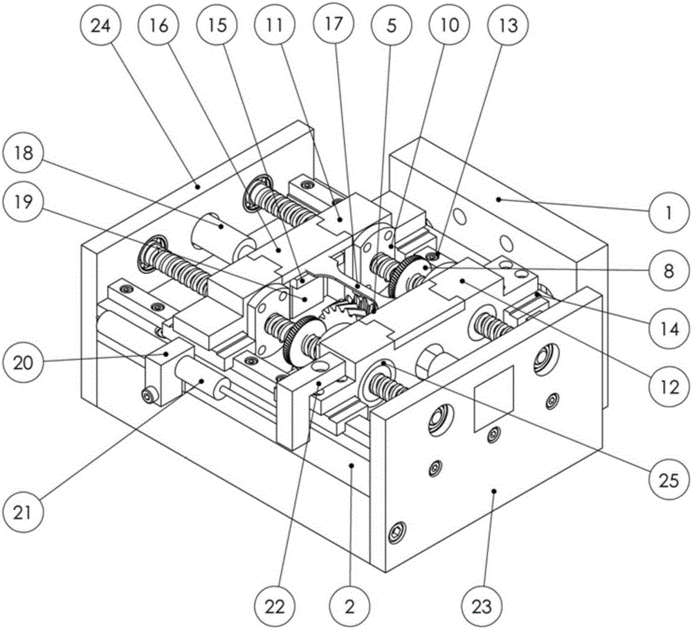
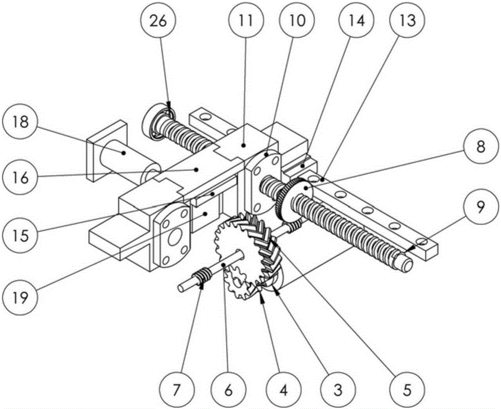
[0034] The invention is an in-situ observation device capable of simultaneously realizing the material structure under two kinds of mechanical performance experiments of tension and compression on the X-ray diffraction experiment equipment. The device can be used for both in-situ observation of tension experiments and in-situ observation of compression experiments. It can be used alone or in combination with X-ray diffraction equipment.

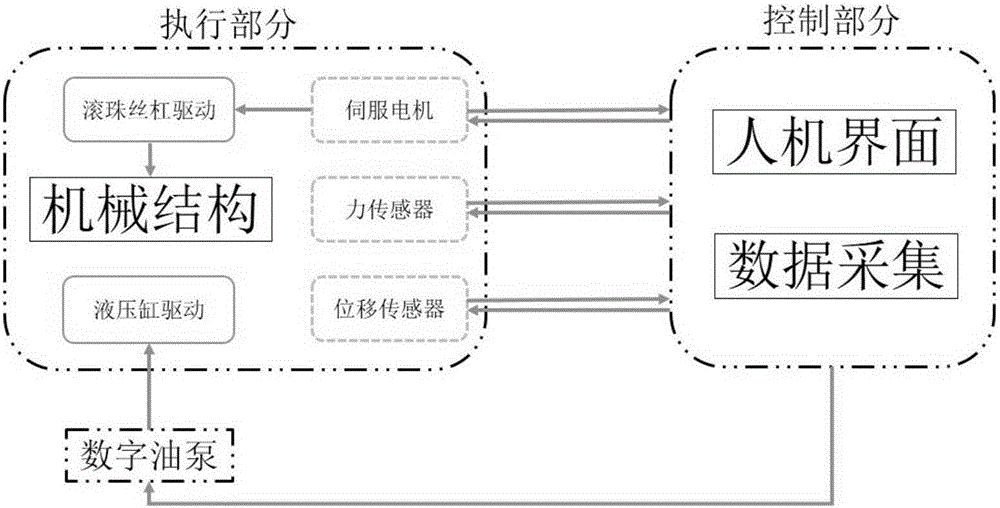
[0035] like figure 1 As shown in -4, the device of the present invention adopts a servo motor and a hydraulic dual drive mode, and the two drive modes can be switched seamlessly. The unit can also be paused at any time. The test device of the present invention comprises the following parts:

[0036] 1. Executing part (located inside the machine)

[0037] The execution part is combined with servo motor drive and hydraulic drive, which rea...


PUM


Abstract

The invention discloses a motor and hydraulic pressure combined drive in-situ test device for the structure properties of materials, and belongs to the technical field of material structure performance in-situ detection. The device comprises an outer frame, left-handed and right-handed ball screws, a moving base A, a moving base B, a sample chuck, a motor drive system and a hydraulic drive system. The device has good experimental equipment compatibility; servo motor and hydraulic pressure dual drive is adopted, tension or pressure force is large, and the strength range of the experimental materials is expanded; the moving distance of the sample chuck is long, and large deformation can be achieved; displacement and force detection precision is high; the deformation rate can be controlled, and displacement or force closed-loop control can be achieved. The device can be used independently or used in cooperation with X-ray diffraction equipment, the problem that only end state detection can be conducted in existing experiments is well solved, and material structure changes in a transient state and material structure changes at special strain points in tension and compression of the sample can be observed in situ.

Description

technical field [0001] The invention relates to the technical field of in-situ detection of material structure performance, in particular to an in-situ test device for material structure performance under the combined drive mode of motor and hydraulic pressure. The device can be used for in-situ observation of tensile experiments and compression experiments. In-situ observation; it can be used alone or in conjunction with X-ray diffraction equipment to realize in-situ observation of the structure and properties of metal materials under both tension and compression experiments. Background technique [0002] X-ray diffraction analysis (X-ray diffraction, referred to as XRD), is the use of X-ray diffraction formed by crystals to analyze the structure of substances in the spatial distribution of internal atoms. The X-ray diffraction method has the advantages of no damage to the sample, no pollution, fast, high measurement accuracy, and a large amount of information about the int...

Claims


Application Information

Patent Timeline
Patent Type & Authority Applications(China)
IPC IPC(8): G01N3/10G01N23/207
Inventor 徐勇马彦张士宏张晓嵩陈大勇
Owner INST OF METAL RESEARCH - CHINESE ACAD OF SCI
Why Eureka
Try Eureka