
A Longitudinal Electro-Optic Modulator with Large Clear Aperture and Large Field of View

An electro-optic modulator and field of view technology, which is applied in the direction of instruments, optics, nonlinear optics, etc., can solve the problems of short light length and unsatisfactory large light aperture, so as to improve transmittance, compensate static phase delay, The effect of a large aperture

Inactive Publication Date: 2017-10-20
ZHONGBEI UNIV
View PDF6 Cites 0 Cited by
  • Summary
  • Abstract
  • Description
  • Claims
  • Application Information

AI Technical Summary

Problems solved by technology

None of the above electro-optic modulators meets the application requirements of large optical aperture, large field of view, short optical length and compact structure.

Method used


Image

  • A Longitudinal Electro-Optic Modulator with Large Clear Aperture and Large Field of View
  • A Longitudinal Electro-Optic Modulator with Large Clear Aperture and Large Field of View
  • A Longitudinal Electro-Optic Modulator with Large Clear Aperture and Large Field of View

Examples


Embodiment Construction

[0028] The following embodiments will further describe the present invention in conjunction with the accompanying drawings.

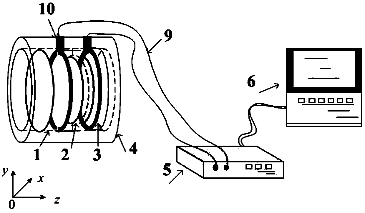
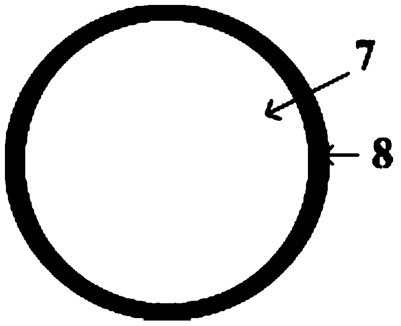
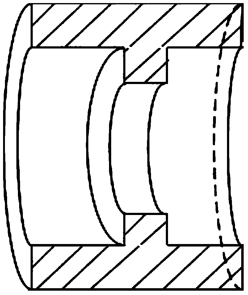
[0029] Such as Figure 1-3 As shown, the present invention provides an electro-optic modulator with large optical aperture, large field of view, short optical length, compact structure, variable phase delay with modulation voltage and uniform modulation. The structure of the electro-optic modulator mainly includes: First electrode 1 , electro-optic crystal 2 , second electrode 3 , holding box 4 , high-voltage driver 5 , and control computer 6 .

[0030] The electro-optic crystal of the electro-optic modulator is selected from DKDP crystal. DKDP belongs to the tetragonal crystal system Crystal type, the crystal axis Z axis is Degree axis, crystal axis X axis and crystal axis Y axis are both 2-degree axes, which are negative uniaxial crystals, and the optical axis is along the direction of the crystal axis Z axis. Its electro-optic coefficient matri...


PUM

PropertyMeasurementUnit
thicknessaaaaaaaaaa
diameteraaaaaaaaaa
thicknessaaaaaaaaaa

Abstract

The invention relates to the technical field of light polarization state modulation, in particular to a longitudinal electro-optical modulator with the large clear aperture and the large field angle. The electro-optical modulator is large in clear aperture and field angle, short in light transmission length, compact in structure, variable in phase delay along with modulation voltage and uniform in modulation. An electro-optical uniaxial crystal with the large electro-optical coefficient is selected as a light transmission crystal, the longitudinal electro-optical effect of the electro-optical crystal is used for manufacturing the electro-optical modulator, the uniaxial crystal with the reciprocal birefringence optical path difference value and electro-optical crystal birefringence optical path difference value is adopted for eliminating static phase delay into which large field angle incident light may be introduced, a transparent electrode is plated and packaging is performed; a configured high voltage driver can select pulse, square wave, sine or direct-current voltage and other output modes for flexible design according to application occasions and a modulation effect needing to be achieved on incident light, and the novel theory and method are provided for the design of a polarized light modulator. The longitudinal electro-optical modulator is mainly applied to the aspects such as pulse laser light source, polarization imaging and optical communication.

Description

technical field [0001] The invention relates to the technical field of light polarization modulation, and more specifically, to a longitudinal electro-optic modulator with a large optical aperture and a large viewing angle. Background technique [0002] The light-passing medium, especially some optical crystals, changes the refractive index ellipsoid under the action of an external electric field and produces a phase delay effect on the incident light, which is called the electro-optic effect. modulation device. According to the refractive index change is proportional to the first power or the second power of the electric field intensity, it is called the primary electro-optic effect (Pockels effect) or the secondary electro-optic effect (Kerr effect); according to the direction of the applied electric field and the direction of light passing parallel or perpendicular, They are also called longitudinal electro-optic effect and transverse electro-optic effect respectively. ...

Claims


Application Information

Patent Timeline
Patent Type & Authority Patents(China)
IPC IPC(8): G02F1/03
CPCG02F1/0316G02F1/0327
Inventor 李克武王志斌李晓陈媛媛李晋华张瑞
Owner ZHONGBEI UNIV
Learn More