Low-leakage-current winding type solid electrolytic capacitor and production method thereof

A technology of solid electrolysis and production method, which is applied in the direction of solid electrolytic capacitors, etc., and can solve problems such as prolonging the production cycle, reducing leakage current, and long impregnation time

Inactive Publication Date: 2016-01-06
HUNAN AIHUA GRP
View PDF5 Cites 12 Cited by
  • Summary
  • Abstract
  • Description
  • Claims
  • Application Information

AI Technical Summary

Problems solved by technology

[0005] However, there is no second formation to repair the oxide film after carbonization, and there is still room for reduction in the leakage current of the product; in addition, the solvent of the impregnation solution is n-butanol, and the impregnation time is longer, prolonging the production cycle

Method used


Image

  • Low-leakage-current winding type solid electrolytic capacitor and production method thereof
  • Low-leakage-current winding type solid electrolytic capacitor and production method thereof

Examples


Embodiment 1

[0023] A kind of production method of winding type solid electrolytic capacitor with low leakage current, it comprises the following steps:

[0024] ⑴ Element preparation: The anode foil riveted with a positive guide pin and the cathode foil riveted with a negative guide pin are wound into a core with electrolytic paper sandwiched between them. The core is formed, carbonized, impregnated with a pretreatment agent, impregnated with a monomer, Impregnated with oxidant and polymerized at high temperature to produce prime;

[0025] The positive guide pin and the negative guide pin are guide pins after formation; the anode foil is formed foil with 1.8 times to 2.0 times the rated voltage of the capacitor, and its surface impurities are Cu 2+ 、Cu + , Fe 3+ , Cl - The sum of the ions is less than 10ppm; the cathode foil is carbon-coated foil, and the thickness of the carbon layer is 45nm; the anode foil and the cathode foil are cut and polished, and the burrs are not greater than ...

Embodiment 2

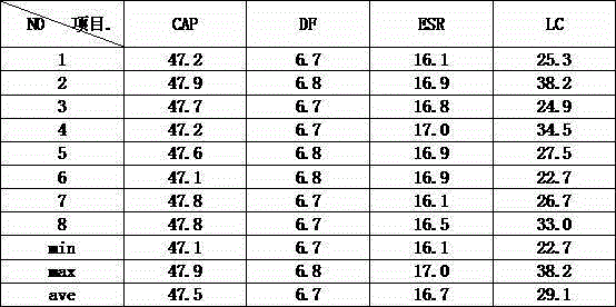
[0050] This embodiment further illustrates the present invention by taking the preparation of a wound-type solid electrolytic capacitor with a specification of 25V47μF as an example.

[0051] During the formation, since the rated voltage of the anode foil in this embodiment is ≥ 25V, the formation is carried out in divided voltage stages. The rated voltage from 25V to the rated withstand voltage of the anode foil (1.88 times the rated voltage of the capacitor) is divided into 4 sections, that is, 25V, 32V, 39V, 47V, and each section is 10min.

[0052] When aging, since the rated voltage of the capacitor is greater than 20V, the aging treatment should be performed at each stage of 20V, 24V, 27V, and 30V for 30 minutes.

[0053] As shown in Table 2, the specification prepared in this example is a 25V47μF winding solid electrolytic capacitor, its capacitance (CAP) is 47.1μF-47.9μF, loss (DF) 6.7-6.8, equivalent series resistance (ESR) 16.1 From mΩ to 17.0mΩ, the characteristics ...


PUM


Abstract

The invention discloses a low-leakage-current winding type solid electrolytic capacitor and a production method thereof. The production method comprises steps of element preparation, assembling, and aging. According to the invention, an anode foil and a cathode foil are cut and then are polished, thereby substantially reducing a short-circuit risk because of puncturing a piece of electrolytic paper by burrs and reducing a risk of an increase of leakage currents due to point discharging. On the basis of impregnation of pre treating agents twice, an oxidation film can be protected well, thereby reducing damages on the oxidation film during a polymerization process. Because an oxidizability group is added into an oxidizing agent, the polymer doping effect is realized and an oxygen-containing agent group having oxidability can be decomposed in a high-temperature de-doping mode, so that the damaged oxidation film can be repaired to a certain extent and the self-healing capability of the capacitor can be improved. According to a prepared solid electrolytic capacitor, a leakage current control standard can be set to be larget value that is not larger than 0.05CV or 15 microamps after charging of 2 min under the temperature of 20+ / -5 DEG C.

Description

technical field [0001] The present invention relates to a solid electrolytic capacitor, in particular to a winding type solid electrolytic capacitor with low leakage current and its production method, in particular to a capacitor whose leakage current is not greater than 0.05CV after charging for 2 minutes at 25±5°C. Low-leakage current wound-type solid electrolytic capacitor with a larger value of 15 μA or larger, and a production method thereof. Background technique [0002] The electrolyte of a solid aluminum electrolytic capacitor is a conductive polymer, which conducts electrons with a conductivity of up to 500 S / m, while the electrolyte of a traditional aluminum electrolytic capacitor conducts ion with low conductivity. Therefore, compared with traditional products, solid aluminum electrolytic capacitors have the advantages of small equivalent series resistance, good high-frequency characteristics and safe use. However, conductive polymers do not have the function of ...

Claims


Application Information

Patent Timeline
Patent Type & Authority Applications(China)
IPC IPC(8): H01G9/15H01G9/042
Inventor 艾立华邹建明李书国刘红宇
Owner HUNAN AIHUA GRP
Why Eureka
Try Eureka