Floating Power Station Base System

A base and power station technology, applied in the field of photovoltaic power generation, can solve problems such as the problem of photovoltaic power station abandoning light being not well solved, limiting the application and development of floating photovoltaic power stations, and failing to utilize water surface resources for photovoltaic power generation, etc., so as to enhance the water retention. , The effect of inhibiting the growth of algae and saving materials

Active Publication Date: 2018-01-19
上海泊屿新能源科技有限公司
View PDF7 Cites 0 Cited by
  • Summary
  • Abstract
  • Description
  • Claims
  • Application Information

AI Technical Summary

Problems solved by technology

However, because the western region is far away from the load center, the problem of solar abandonment of photovoltaic power plants in some regions has not been well resolved.
[0005] At present, foreign countries and domestics basically use large-scale ground photovoltaic power plants to generate electricity and rooftop photovoltaic power generation models, and hardly use water surface resources for photovoltaic power generation. The only design is to build a floating body composed of several small floating bodies on the water. For the floating platform with gaps, photovoltaic panels are directly laid on the floating platform or metal brackets are built on the floating platform to install photovoltaic panels. Such a design scheme is not effective in wind pressure and wave resistance, and uses the principle of air cooling, resulting in The power generation efficiency of photovoltaic panels is not high, which has always limited the application and development of photovoltaic power plants on water

Method used


Image

  • Floating Power Station Base System
  • Floating Power Station Base System
  • Floating Power Station Base System

Examples


Embodiment Construction

[0043] The present invention will be described in detail below in conjunction with specific embodiments. The following examples will help those skilled in the art to further understand the present invention, but do not limit the present invention in any form. It should be noted that those skilled in the art can make several modifications and improvements without departing from the concept of the present invention. These all belong to the protection scope of the present invention.

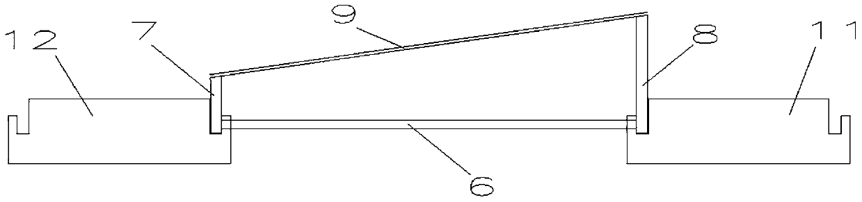
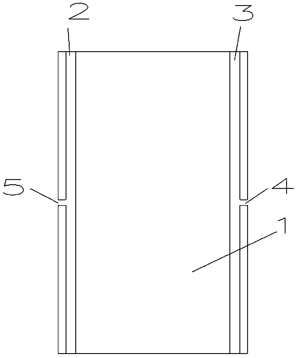
[0044] According to the floating power station base system provided by the present invention, it includes a buoyant tank 1, and there are more than two buoyant tanks 1, and the two ends or two sides of the top surface of the buoyant tank 1 are respectively provided with a front support 7 and a rear support 8 , and every two buoyant tanks 1 form a platform unit, and the buoyant tanks 1 of the same platform unit are connected by several connecting pieces 6 .

[0045] It also includes a photovoltaic ...


PUM


Abstract

The invention provides a floating power station base system. The floating power station base system comprises buoyancy tanks (1), two ends of the top surface or two side surfaces of each buoyancy tank (1) are provided with photovoltaic plate installation parts, each two buoyancy tanks (1) form a platform unit, the buoyancy tanks (1) of the same platform units are connected via a plurality of connecting pieces (6), and the adjacent platform units are connected in a fastening manner via the connecting pieces or matching structures on adjacent side surfaces of the buoyancy tanks (1). According to the floating power station base system, a photovoltaic plate (9) is arranged above a water area between the two buoyancy tanks (1), double continuous circulation cooling of the photovoltaic plate is realized by fully employing the continuous circulation water-cooling principle between the photovoltaic plate and the water surface, the output power of the photovoltaic plate is increased, and the lifetime of the material of the photovoltaic plate is extended.

Description

technical field [0001] The present invention relates to photovoltaic power generation, in particular to a floating power station base system. Background technique [0002] my country is one of the few countries in the world that uses coal as the main energy source. About 65% of primary energy production and consumption is coal, and a large amount of coal is used, so that 66% of China's urban air particulate matter content and 22% of urban air sulfur dioxide content exceed The national air quality secondary standard. The use of coal and fossil energy emits a large amount of pollutants, leading to air pollution and acid rain pollution, which has seriously deteriorated the air quality of Chinese cities. China has 16 of the 20 most polluted cities in the world listed in the 2001 World Bank Development Report. In areas with severe air pollution, the total mortality and incidence of respiratory diseases are higher than those in lightly polluted areas. Symptoms of chronic bronchi...

Claims


Application Information

Patent Timeline
Patent Type & Authority Patents(China)
IPC IPC(8): H02S20/00H02S20/30H02S40/42
CPCH02S20/00Y02E10/50
Inventor 蒋勇贺飞赵书恒刘洋尹明鹏
Owner 上海泊屿新能源科技有限公司
Why Eureka
Try Eureka