Small ball head tool single-turntable polishing machining device and tool setting method
A processing device and tool technology, which is applied in the field of small ball head tool single turntable grinding and polishing processing device, can solve the problems of low tool efficiency, difficult to achieve high-precision tool setting, long tool setting time, etc., and achieve high-efficiency tool setting adjustment Effect
- Summary
- Abstract
- Description
- Claims
- Application Information
AI Technical Summary
Problems solved by technology
Method used
Image
Examples
specific Embodiment approach 1
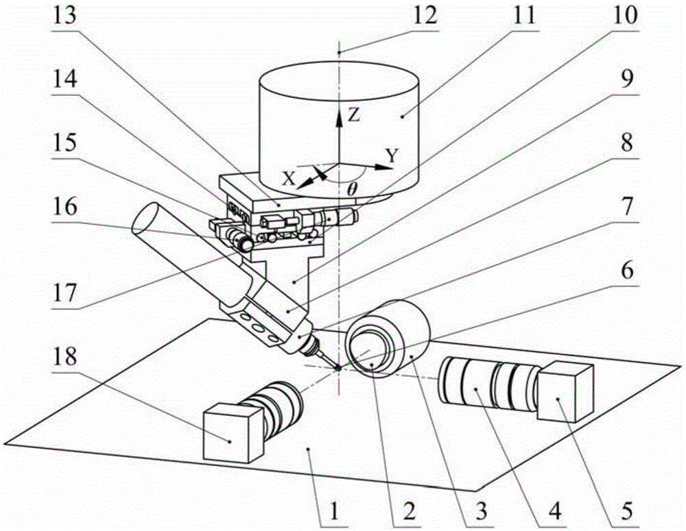
[0031] Specific implementation mode one: combine figure 1 Describe this embodiment, a small ball head tool single turntable grinding and polishing processing device and tool setting method, the device includes a horizontal platform 1, a workpiece spindle 3, a first CCD camera 5, a small ball head grinding and polishing tool 6, a grinding Throwing tool spindle 7, spindle clamping part 8, bevel fixed seat 9, centering adjustment displacement table 10, turntable 11, connecting plate 13, V-direction roller guide rail 14, U-direction roller guide rail 15, U-direction adjustment micrometer Head 16, V adjust micrometer head 17, the second CCD camera 18 and two magnifying lens 4; One magnifying lens 4 is installed on the first CCD camera 5, and another magnifying lens 4 is installed on the second CCD camera 18, The workpiece 2 is installed on the workpiece spindle 3, the first CCD camera 5, the second CCD camera 18 and the workpiece spindle 3 are arranged on the horizontal platform, t...
specific Embodiment approach 2
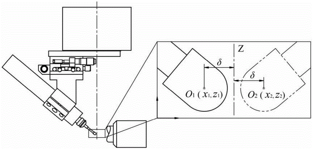
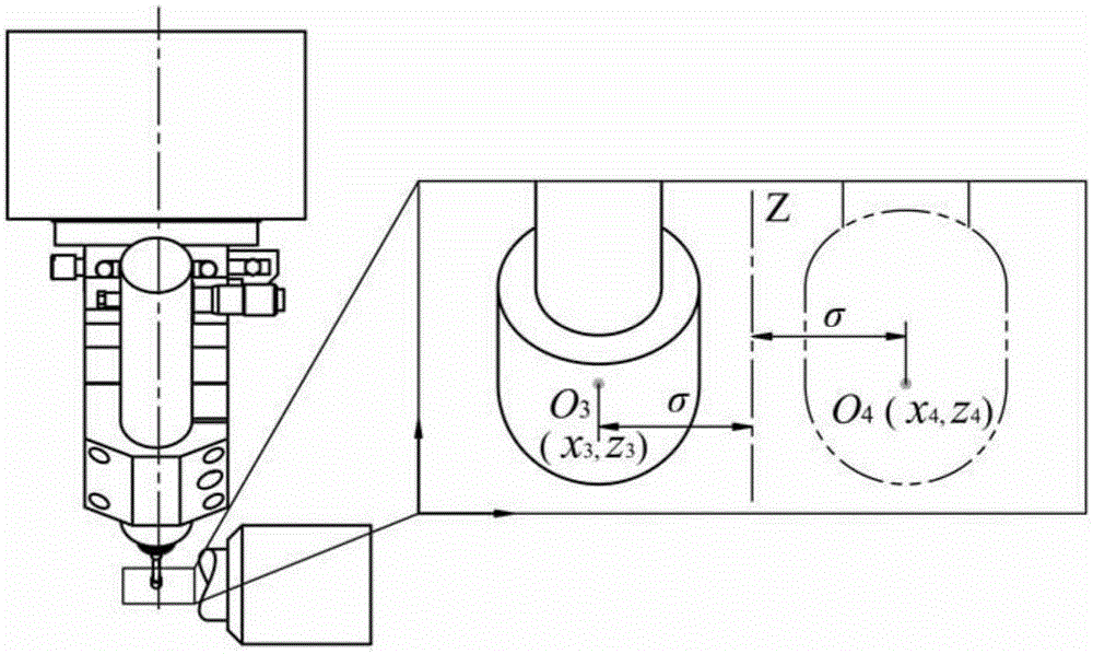
[0033] Specific implementation mode two: combination Figure 1-Figure 4 , Figure 7 Describe this embodiment, a small ball head tool single turntable grinding and polishing processing device and tool setting method, the centering adjustment and tool setting method of the tool relative to the turntable is realized according to the following steps:
[0034] Use the first CCD camera 5 to obtain the tool setting image of the small ball head polishing tool 6 in the tool setting area, first set the swing angle θ of the turntable 11 to 90° and -90°, and process the tool setting image captured by the first CCD camera 5 Image, obtain the pixel coordinates of the center point of the small ball head polishing tool 6 in the image, and obtain the centering deviation value of the center point of the small ball head polishing tool 6 in the direction of the V-direction roller guide rail 14 according to the calibration coefficient of the image system δ, and eliminate the deviation by fine-tun...
specific Embodiment approach 3
[0045] Specific implementation mode three: combination figure 1 , Figure 4-Figure 7 Describe this embodiment, a small ball head tool single turntable grinding and polishing processing device and tool setting method, the tool setting method of the tool relative to the workpiece is realized according to the following steps:
[0046] First, the second CCD camera 18 is used to obtain the image of the tool setting area from the X-axis direction to obtain the relative position deviation between the center of the tool head and the workpiece axis in the Y and Z directions, and then the first CCD camera 5 is used to obtain the image of the tool from the Y-axis direction. The position deviation of the head center relative to the end surface of the workpiece in the X direction, and then the CNC axis of the machine tool drives the workpiece 2 and the tool system to move along the X, Y, and Z directions respectively to adjust the tool and the workpiece 2 to the origin of the machining pro...
PUM
 Abstract
Description
Claims
Application Information
 - R&D
- Intellectual Property
- Life Sciences
- Materials
- Tech Scout
- Unparalleled Data Quality
- Higher Quality Content
- 60% Fewer Hallucinations
Browse by: Latest US Patents, China's latest patents, Technical Efficacy Thesaurus, Application Domain, Technology Topic, Popular Technical Reports.
© 2025 PatSnap. All rights reserved.Legal|Privacy policy|Modern Slavery Act Transparency Statement|Sitemap|About US| Contact US: help@patsnap.com


