RFID printed antenna hot stamped electronic tag and manufacturing method thereof

A technology for printing antennas and electronic labels, which is applied to record carriers, instruments, and computer parts used in machines. It can solve problems such as inability to meet customer needs, and achieve the effect of avoiding a large number of imitations, stable performance, and increasing aesthetics.

Active Publication Date: 2016-01-13
SHANDONG TAIBAO PREVENTING COUNTERFEIT
View PDF6 Cites 20 Cited by
  • Summary
  • Abstract
  • Description
  • Claims
  • Application Information

AI Technical Summary

Problems solved by technology

However, pure hot stamping technology can no longer meet the cu

Method used


Image

  • RFID printed antenna hot stamped electronic tag and manufacturing method thereof

Examples


Embodiment 1

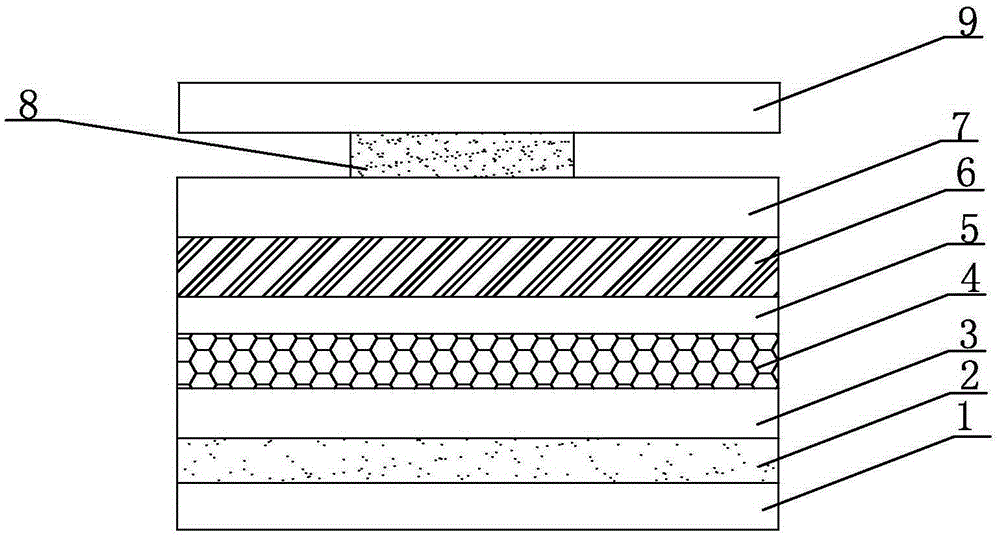
[0054] An RFID printing antenna hot stamping electronic label, such as figure 1 As shown, a PET substrate layer 1 is included, and a release layer 2, an information layer 3, a printing layer 4, a first adhesive layer 5, an antenna substrate layer 6, and a printed antenna layer 7 are sequentially arranged on the PET substrate layer 1 from bottom to top. The chip 8 is packaged upside down on the printed antenna layer 7 , and the second glue layer 9 is arranged on the chip 8 .

[0055] A method for preparing an RFID printing antenna hot stamping electronic label, comprising the following steps:

[0056] 1. Select a 30um base material PET to coat the release layer, and use a coating machine to coat the release layer and the information layer (color layer) on it. The release layer coating solution is coated with 4 cups and has a viscosity of 20s. After testing, the release layer The thickness of the type layer is 1.5um, and the 180-degree peel strength of the release layer is 0.00...

Embodiment 2

[0066] An RFID printing antenna hot stamping electronic label, such as figure 1 As shown, a PET substrate layer 1 is included, and a release layer 2, an information layer 3, a printing layer 4, a first adhesive layer 5, an antenna substrate layer 6, and a printed antenna layer 7 are sequentially arranged on the PET substrate layer 1 from bottom to top. The chip 8 is packaged upside down on the printed antenna layer 7 , and the second glue layer 9 is arranged on the chip 8 .

[0067] A method for preparing an RFID printing antenna hot stamping electronic label, comprising the following steps:

[0068] 1. Select a 50um double-sided corona-free substrate PET to coat the release layer, and use a coating machine to coat the release layer and the information layer (color layer) on it. The release layer coating liquid is coated with 4 cups of viscosity. 22s, the thickness of the release layer is 2.1um, and the 180-degree peel strength of the release layer is 0.002KN / m;

[0069] 2. ...


PUM

PropertyMeasurementUnit
Thicknessaaaaaaaaaa
Thicknessaaaaaaaaaa
Peel strengthaaaaaaaaaa

Abstract

The invention belongs to the field of information technology and anti-counterfeiting printed antennas, and particularly relates to an RFID printed antenna hot stamped electronic tag and a manufacturing method thereof. The electronic tag comprises a PET substrate layer; a release layer, an information layer, a printing layer, a first glue layer, an antenna substrate layer and a printed antenna layer are sequentially from bottom to top arranged on the PET substrate layer; flip chip packaging is carried out on the printed antenna layer, and a second glue layer is arranged on the chip. The PET is selected to serve as the substrate, and the release layer and the information layer are coated on the PET substrate layer; teletext information is then printed, glue is applied, the antenna substrate is printed, conductive oil ink is then printed, flip chip packaging is then carried out on the well-printed antenna, glue is then applied, and after being dried, the tag is transferred to a stuck object in a hot stamping mode. Organic combination between the hot stamping technology and the electronic tag can be realized, the manufactured electronic tag has stable performance, environmental protection is realized, the cost is low, the manufacturing process is relatively simple, the appearance is attractive, damage is not likely to happen, double counterfeiting prevention can be realized, and the anti-counterfeiting force is improved.

Description

technical field [0001] The invention belongs to the fields of information technology and anti-counterfeit printing antennas, and in particular relates to an RFID printing antenna hot stamping electronic label and a preparation method thereof. Background technique [0002] The printed antenna is an antenna formed by printing conductive lines on an insulating substrate (film) with conductive ink. Conductive ink, also known as conductive adhesive, is a special ink that allows current to flow. It is composed of dispersed fine conductive particles and conductive polymers. (such as conductive silver paste, etc.), printed on flexible or hard substrates to make printed circuits, which play the role of wires, antennas and resistors. Printed antennas have begun to replace etching antennas in various frequency bands, such as UHF (860MHz~960MHz) and microwave frequency (2.45GHz), due to their advantages of environmental protection, low cost, and convenient production. In terms of antenn...

Claims


Application Information

Patent Timeline
IPC IPC(8): G06K19/077
Inventor 巩端洲张钦永许丕刚巩坤巩龙贤
Owner SHANDONG TAIBAO PREVENTING COUNTERFEIT
Why Eureka
Try Eureka