Oxide cathode

An oxide cathode and cathode technology, which is used in the manufacture of cold cathodes, solid thermionic cathodes of discharge tubes, and main electrodes of discharge tubes, etc., can solve the problems of residual emitters, geometric defects, easy ignition, etc. The effect of lifespan, increased bombardment ability, and reduced chance of ignition

Active Publication Date: 2016-01-13
甘肃虹光电子有限责任公司
View PDF8 Cites 5 Cited by
  • Summary
  • Abstract
  • Description
  • Claims
  • Application Information

AI Technical Summary

Problems solved by technology

Although these methods have improved the roughness and flatness of the surface of the cathode emission layer, the surface of the emission layer is still not smooth, there are certain geometric defects, and there are emitter residues on the surface of the non-emission layer.
The cathode has poor anti-particle bombardment performance, it is easy to spark during work, and there is stray current, which affects the stability and life of the cathode.

Method used


Image

  • Oxide cathode
  • Oxide cathode
  • Oxide cathode

Examples


Embodiment Construction

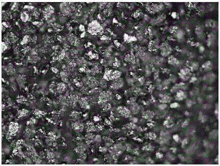
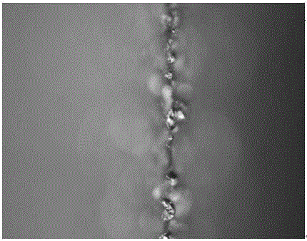
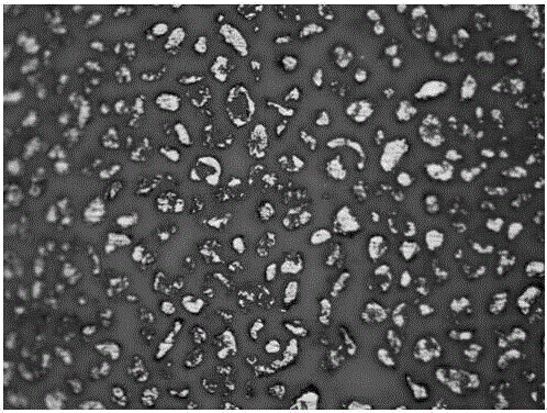
[0022] An oxide cathode: ①Reserve a geometric margin of (0.1-0.15) mm on the peripheral surface of the emission layer to make the cathode (tungsten-based) metal. Clean and degas the cathode base metal. ②Pour nickel powder 1 (purity ≥ 99.9%) with an average particle size of 40 μm (minimum not exceeding 20 μm, maximum not exceeding 60 μm) on the cathode base metal by molding. Put the cathode base metal 3 filled with nickel powder 1 together with the mold in a hydrogen furnace and sinter at a temperature of (1250±20)°C for 20 minutes (hydrogen flow rate ≥0.4L / min, dew point ≤-65°C), after cooling mold. Such as figure 2 As shown, the surface of the finished nickel sponge layer should have a geometric margin of 0.3-0.4 mm higher than the base metal (the actual size higher than the base metal should be the 0.3-0.4 mm above minus the reserved surface of the emissive layer. The difference of 0.1 ~ 0.15mm), the hole size is between (45% ~ 50%) ( figure 2 , image 3 , Figure 4 ...


PUM


Abstract

The invention provides an oxide cathode, which particularly comprises the following steps: preparing a cathode-based metal, and reserving a geometric margin on the peripheral surface of an emission layer; pouring nickel powder onto the cathode-based metal by a molding method and putting the entire cathode-based metal together with a mold into a hydrogen furnace for sintering into a nickel sponge layer, reserving a certain geometric margin on the prepared nickel sponge layer, filling the nickel sponge layer with alkali earth metal carbonate, mechanically compacting an emission surface of a cathode emission layer, and removing the residual geometric margin; carrying out pre-decomposition on the oxide cathode before pipe filling; and clamping the oxide cathode on a chuck of a lathe, turning the emission layer and the peripheral surface, removing the residual geometric margin, and then wiping away all particles attached to the cathode surface. The cathode surface provided by the invention becomes smooth, regular, bright and clean; a hot particle emission angle is reduced; deformation of emission electron density distribution is limited; the particle bombardment resistance of the cathode is improved; the sparking probability of the cathode emission surface is reduced; the work stability of the cathode is improved; and the lifetime of the cathode is prolonged.

Description

technical field [0001] The invention relates to electrical components, in particular to an oxide cathode. Background technique [0002] The widespread practice of oxide cathode manufacturing is to prepare a metal sponge layer on the base metal (nickel or tungsten) by molding, and then fill the sponge layer with alkaline earth metal carbonates (binary salt barium carbonate, strontium carbonate; ternary salt Barium carbonate, strontium carbonate, calcium carbonate; quaternary salt barium carbonate, strontium carbonate, calcium carbonate, scandium oxide) to make the emission layer, pre-decompose before use. The flatness, roughness, and cleanliness of the surface of the oxide cathode emission layer directly affect the current size, stability, density distribution and cathode life of the emitted electrons. In order to improve the physical state of the surface of the emission layer, there are two methods disclosed: one method is to divide the emission layer into a top layer a...

Claims


Application Information

Patent Timeline
Patent Type & Authority Applications(China)
IPC IPC(8): H01J1/14H01J1/20H01J9/02
Inventor 何擎
Owner 甘肃虹光电子有限责任公司
Why Eureka
Try Eureka