Eureka AIR delivers breakthrough ideas for toughest innovation challenges, trusted by R&D personnel around the world.

Hot press molding method for spherical head made of 10CrNi3MoV steel

A technology of spherical head and hot press forming, which is applied in the direction of furnace type, heat treatment furnace, heat treatment equipment, etc., and can solve the problems of high cost and difficult processing stress

Inactive Publication Date: 2016-01-20
WUCHANG SHIPBUILDING IND
View PDF5 Cites 3 Cited by
  • Summary
  • Abstract
  • Description
  • Claims
  • Application Information

AI Technical Summary

Problems solved by technology

[0003] The invention provides a 10CrNi3MoV steel spherical head hot-press forming method, which solves the problems of high cost and difficult elimination of processing stress in the existing spherical head cold forming process, so as to reduce the cost and improve the service life of the 10CrNi3MoV steel spherical head

Method used


Image

  • Hot press molding method for spherical head made of 10CrNi3MoV steel
  • Hot press molding method for spherical head made of 10CrNi3MoV steel

Examples


Embodiment 1

[0015] Embodiment 1, comprises the following steps:

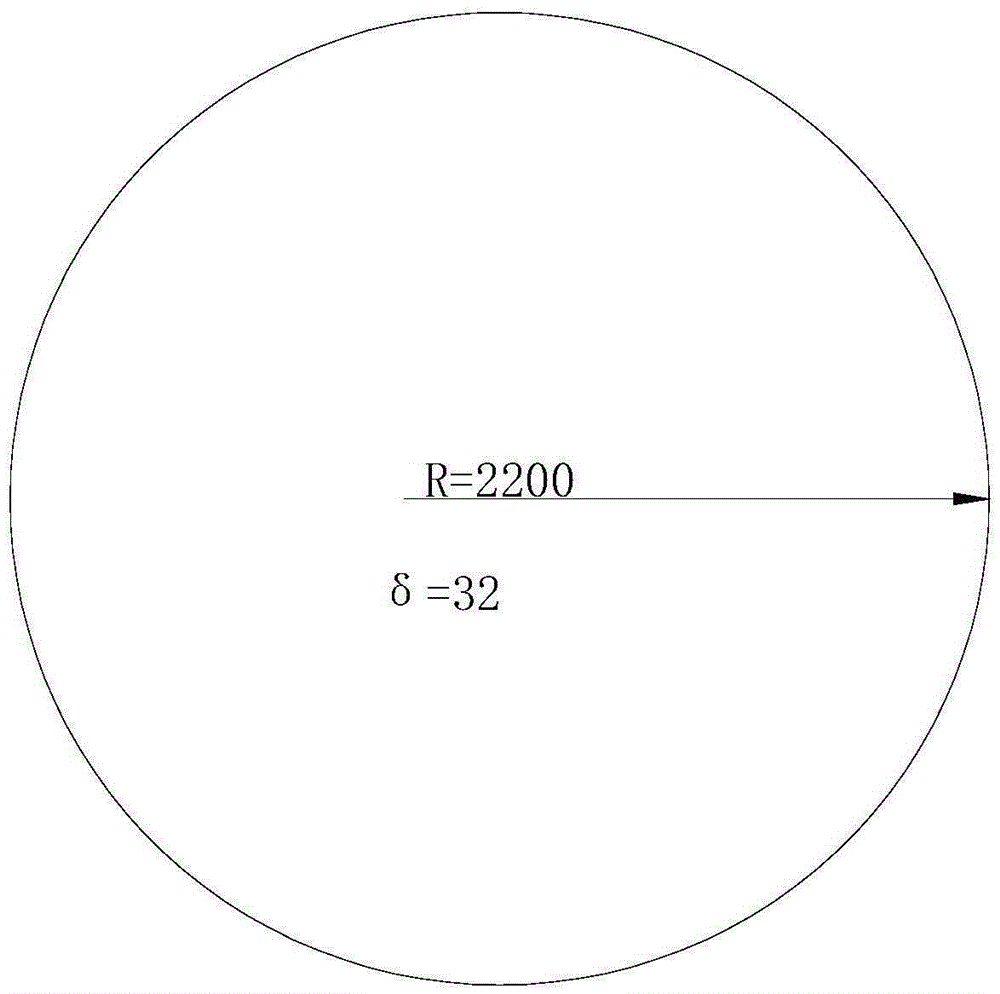
[0016] (1) disc heating step: put figure 1 The 10CrNi3MoV steel disc shown is put into the heating furnace. The temperature of the furnace is 750°C when the furnace is installed. The steel circular plate is heated evenly to avoid over-burning of the material or insufficient holding time; the radius R of the 10CrNi3MoV steel circular plate is 2200mm, and the thickness δ 1 32mm;

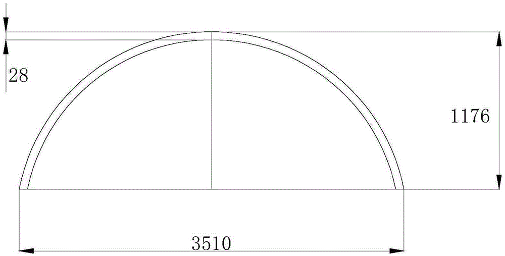
[0017] (2) Compression molding step: transfer the heated 10CrNi3MoV steel circular plate to the platform of the punching machine, and align the mold on the punching machine with the center of the 10CrNi3MoV steel circular plate for stamping. The stamping start temperature is 860°C, and the final pressing temperature is 750°C. formed as figure 2 The 10CrNi3MoV steel spherical head shown in the figure; then demoulding at a temperature of 720°C, the demoulded 10CrNi3MoV steel spherical head is cooled to 480°C and lifted off the workbench, and coole...

Embodiment 2

[0020] Embodiment 2, comprises the following steps:

[0021] (1) Disc heating step: Put the 10CrNi3MoV steel disc into the heating furnace. The furnace temperature is 780°C when the furnace is installed, and the temperature is raised at a rate of 135°C / hour after the furnace is installed. When the temperature reaches 940°C±20°C, keep it for 45 minutes ; When heating, it should be ensured that the 10CrNi3MoV steel disc is heated evenly to avoid overburning of the material or insufficient holding time; the radius R of the 10CrNi3MoV steel disc is 1800mm, and the thickness δ 1 34mm;

[0022] (2) Compression molding step: transfer the heated 10CrNi3MoV steel circular plate to the platform of the punching machine, and align the mold on the punching machine with the center of the 10CrNi3MoV steel circular plate for stamping. The starting temperature of stamping is 940°C, and the final pressing temperature is 800°C. Form a 10CrNi3MoV steel spherical head; then demould at a temperatu...


PUM

PropertyMeasurementUnit
yield strengthaaaaaaaaaa
thicknessaaaaaaaaaa
depthaaaaaaaaaa

Abstract

The invention provides a hot press molding method for a spherical head made of 10CrNi3MoV steel and belongs to the field of machining and manufacturing methods of end sockets of sealing pressure structures of ship bathyscaphs. The problems that an existing spherical head cold machining and forming process is high in cost and machining stress is difficult to eliminate are solved, so that cost is reduced, and the service life of the spherical head made of the 10CrNi3MoV steel is prolonged. The method includes the round plate heating step, the die forming step, the quenching treatment step and the tempering treatment step. By the adoption of the method, the requirements for pressing die and stamping equipment are lowered, stamping forming is easy to control, quality is better, machining stress does not exist, it can be guaranteed that the mechanical performance of the spherical head made of the 10CrNi3MoV steel is identical to that of the 10CrNi3MoV steel plate, and therefore it is guaranteed that the service life of the spherical head made of the 10CrNi3MoV steel is identical to that of a ship.

Description

technical field [0001] The invention belongs to a method for processing and manufacturing a head of a sealing pressure structure of a ship type deep submersible, in particular to a method for hot-pressing a 10CrNi3MoV steel spherical head. Background technique [0002] The sealing pressure structure of marine submersibles is sealed by a spherical head. 10CrNi3MoV steel is a low-alloy high-strength steel, which is used for ship structures. Its yield strength is greater than or equal to 590MPa, and it is difficult to process. The existing 10CrNi3MoV steel spherical head is generally formed by cold pressing (molding). This type of forming process has high requirements on the die and cold pressing equipment, which brings high cost and processing stress to the manufacturing of the single-piece spherical head. It is also difficult to eliminate, reducing the service life of the spherical head. Contents of the invention [0003] The invention provides a 10CrNi3MoV steel spherical...

Claims


Application Information

Patent Timeline
Patent Type & Authority Applications(China)
IPC IPC(8): C21D8/00C21D9/00C21D6/00
Inventor 王波
Owner WUCHANG SHIPBUILDING IND
Why Eureka
Eureka Blog
Learn More