Angular displacement detecting method for adaptive optics system, imaging magnification detecting method for adaptive optics system, and adaptive optics system
A technology of adaptive optics and detection methods, which is applied in optical instrument testing, optical radiation measurement, optics, etc., can solve the problems of compensating the influence of optical precision and inaccurate correspondence, and achieve the effect of easy detection
- Summary
- Abstract
- Description
- Claims
- Application Information
AI Technical Summary
Problems solved by technology
Method used
Image


Examples
no. 1 approach
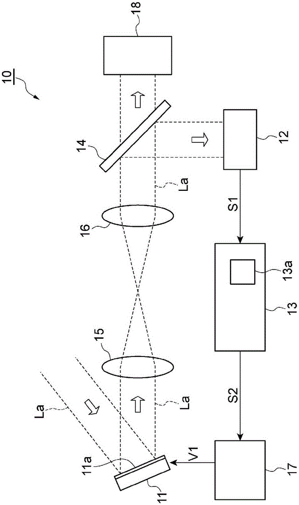
[0072] figure 1 It is a diagram schematically showing the configuration of the adaptive optics system 10 of this embodiment. The adaptive optics system 10 can be assembled in, for example, an ophthalmological inspection device, a laser processing device, a microscope device, or a compensation optical device. The adaptive optics system 10 includes: a spatial light modulator (SLM) 11, a wavefront sensor 12, a control unit 13, a beam splitter 14, relay lenses 15 and 16, and a control circuit unit 17.
[0073] In the spatial light modulator 11, an optical image La is received on a modulation surface 11a displaying a phase pattern, and the wavefront shape of the optical image La is modulated and output. The optical image La incident on the spatial light modulator 11 is light emitted from, for example, a laser light source or a super luminescent diode (SLD), or reflected light, scattered light, fluorescence, etc., generated from an observation object irradiated with light. The wavefro...
no. 2 approach
[0144] In the first embodiment described above, in the light intensity distribution acquisition step S13, the light intensity distribution data D is acquired in a state where the first phase pattern having linearity in at least one direction is displayed in the regions B1 and B2. A . However, the first phase patterns displayed in the areas B1 and B2 do not necessarily need to be displayed at the same time, and the above-mentioned embodiment can be modified as follows.
[0145] Figure 21 It is a flowchart showing the angle deviation detection method and the operation of the control unit 13 of the second embodiment. This embodiment is different from the above-mentioned first embodiment in that it includes steps S21-24 instead of Figure 20 Steps S12 and S13 are shown. In addition, the other steps are the same as the above-mentioned first embodiment, and therefore, detailed descriptions are omitted.
[0146] In step S21, the control unit 13 creates a special phase pattern P for dete...
no. 3 approach
[0153] In the above-mentioned first and second embodiments, the first phase pattern having linearity in at least one direction is displayed in two regions B1 and B2, and the angular deviation is obtained based on the relative positional relationship of the convergent spot P corresponding to these regions the amount. The angle deviation detection method and the adaptive optical system 10 of one aspect of the present invention can obtain the angle deviation amount even if it is the method described below. In addition, the configuration of the adaptive optics system 10 other than the operation of the control unit 13 is the same as that of the first embodiment described above.
[0154] Figure 24 It conceptually shows the special phase pattern P displayed on the modulation surface 11a in this embodiment for detecting the amount of angular deviation D Figure. Such as Figure 24 As shown, the phase pattern P D It includes three regions B6 to B8 that are arranged in a row in a certain ...
PUM
 Abstract
Description
Claims
Application Information
 - R&D
- Intellectual Property
- Life Sciences
- Materials
- Tech Scout
- Unparalleled Data Quality
- Higher Quality Content
- 60% Fewer Hallucinations
Browse by: Latest US Patents, China's latest patents, Technical Efficacy Thesaurus, Application Domain, Technology Topic, Popular Technical Reports.
© 2025 PatSnap. All rights reserved.Legal|Privacy policy|Modern Slavery Act Transparency Statement|Sitemap|About US| Contact US: help@patsnap.com