
A handheld plastic optical fiber end face processing device and processing method

A plastic optical fiber and end-face processing technology, applied in the field of optical fiber production, can solve the problems of large insertion loss and return loss, unfavorable communication quality, single function, etc., to reduce insertion loss and return loss, widen the scope of use, and easy to use. Effect

Active Publication Date: 2018-02-23
JIANGSU HENGTONG OPTICAL FIBER TECH
View PDF5 Cites 2 Cited by
  • Summary
  • Abstract
  • Description
  • Claims
  • Application Information

AI Technical Summary

Problems solved by technology

[0003] However, for the end-face treatment of plastic optical fibers or optical cables for communication that require low insertion loss and return loss, the end-face treatment method of plastic optical fibers for lighting is relatively rough, and because plastic optical fibers or optical cables are often cut and used For the brittle plastic optical fiber, only using special scissors to cut the end face does not guarantee that the end face is straight and free of defects. The insertion loss and return loss are often large, which is not conducive to the improvement of communication quality.
[0004] At the same time, the commonly used end-face processing tools are aimed at silica optical fibers, and there is no special tool for plastic optical fiber end-face processing.
Due to the significant difference in the material of plastic optical fiber and quartz optical fiber, the end-face treatment of quartz optical fiber is not suitable for plastic optical fiber, and they are all desktop, with large volume, complex structure and single function, which is not conducive to outdoor construction

Method used


Image

  • A handheld plastic optical fiber end face processing device and processing method
  • A handheld plastic optical fiber end face processing device and processing method

Examples


Embodiment 1

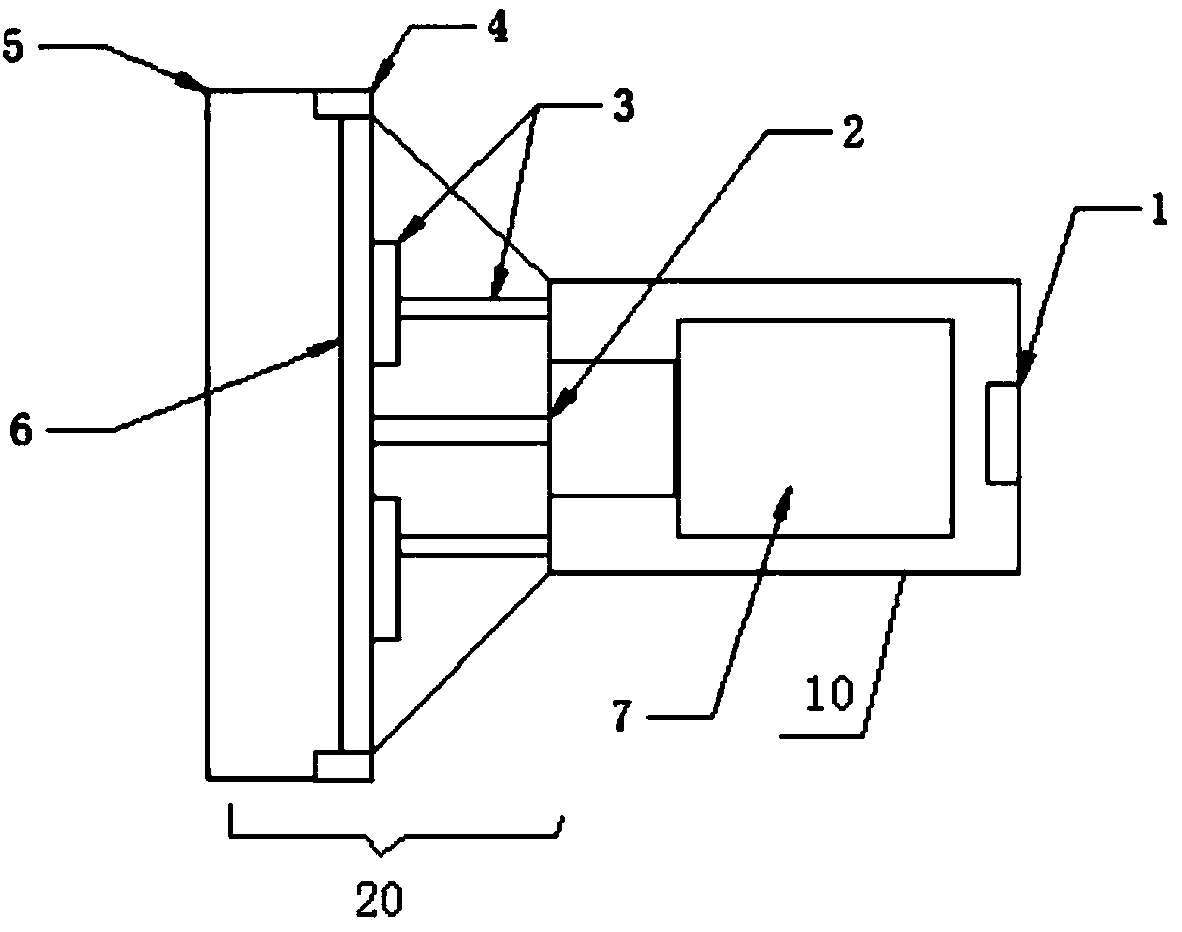
[0030] Such as figure 1 As shown, this embodiment discloses a hand-held plastic optical fiber end-face processing device, which includes a hand-held end housing 10 and an end-face processing assembly housing 20 connected to one end of the hand-held end housing 10. In order to facilitate the hand-held use of the device , the shape of the device can be set to look like a flashlight. In other embodiments, there can be other shape structures, which are not limited here.

[0031] In this embodiment, a micromotor 2 and a 12V rechargeable battery pack 7 are arranged inside the above-mentioned hand-held terminal housing 10, and the above-mentioned 12V rechargeable battery pack 7 supplies power for the above-mentioned micromotor 2, and the charging port 1 of the above-mentioned 12V rechargeable battery pack 7 is arranged on The end of the above-mentioned handheld terminal housing 10 . The output end of the micro motor 2 is connected with a polishing assembly, and the micro motor 2 dri...

Embodiment 2

[0040] The structure of the hand-held plastic optical fiber end face treatment device disclosed in Example 2 is the same as that disclosed in Example 1. The difference is that the heating element 3 in Example 2 is selected as a heating resistor, and the heat conducting element 6 is selected as smooth iron plate.

[0041] The above-mentioned device can realize the functions of polishing and thermoforming the plastic optical fiber at the end of the single-core and double-core plastic optical fiber cable, and effectively reduces the insertion loss and return loss of the ready-to-use communication plastic optical fiber or optical cable.


PUM


Abstract

The invention relates to a hand-held plastic fiber end face processing apparatus. The hand-held plastic fiber end face processing apparatus comprises a hand-held end housing and an end face processing assembly housing, wherein a micromotor, heating members and a heat conduction member are arranged in the hand-held end housing; the other end of the end face processing assembly housing is detachably provided with a plastic fiber fixing piece; the output end of the micromotor is connected with the heat conduction member; a piece of sand paper is arranged on the heat conduction member; the plastic fiber fixing piece can fix a plastic fiber to be processed; when the micromotor drives the heat conduction member to rotate, the sand paper is driven to polish the plastic fiber end face; when the plastic fiber end face is polished and becomes smooth, the heating members are energized to heat the heat conduction member; the heat conduction member transfers the heat to the plastic fiber; and the plastic fiber is pasted on the heat conduction member for completing thermoplastic moulding. The hand-held plastic fiber end face processing apparatus can realize polishing and thermoplastic moulding functions for the plastic fiber at single-core and double core plastic optical cable end, and can effectively reduce the insertion loss and return loss of a communication plastic optical fiber or cable which is ready to use after cutting.

Description

technical field [0001] The invention belongs to the field of optical fiber production, in particular to a plastic optical fiber processing device, in particular to a hand-held plastic optical fiber end face processing device and a processing method. Background technique [0002] Plastic optical fiber (POF) is an optical fiber with a core layer made of highly transparent polymers such as polymethyl methacrylate (PMMA) and fluorine-containing plastics. Compared with silica optical fiber, plastic optical fiber is light, soft, and more resistant to bending and vibration. At the same time, because of its large core and easy coupling, it does not require very careful end-face treatment like silica optical fiber during use. In plastic optical fibers for lighting, construction personnel often only need to use scissors and sandpaper to simply process the end faces of plastic optical fibers or optical cables. [0003] However, for the end-face treatment of plastic optical fibers or o...

Claims


Application Information

Patent Timeline
Patent Type & Authority Patents(China)
IPC IPC(8): G02B6/25
CPCG02B6/25
Inventor 黄秋实王建江郝昌平陈伟贺作为张良
Owner JIANGSU HENGTONG OPTICAL FIBER TECH
Learn More